A single rigid body held by two supports is not much of a structure, and the equilibrium conditions of the previous lesson gave only the reactions from the ground. Real structures are assemblies, and the oldest efficient assembly is the truss: a framework of straight bars joined at their ends into a pattern of triangles.
Why triangles
Take four bars pinned into a quadrilateral. Nothing prevents it collapsing into a parallelogram and then into a flat line, because the bars keep their lengths while the angles change freely. Take three bars pinned into a triangle and the shape is fixed, since the three side lengths determine the three angles completely. That is the whole reason a truss is drawn as triangles.
The engineering payoff is not stiffness for its own sake. In a triangulated frame with the loads applied at the joints, every bar carries force along its own length and nothing else, which is the most efficient way a piece of material can be used: the stress is the same at every point of the cross section, so no part of the bar is idle. A beam of the same span and depth uses its material far less evenly, which is why a railway bridge of 60 metres is a truss and a floor joist of 6 metres is not. The truss wins when the span is long enough that the beam's wasted material outweighs the cost of making dozens of connections.
Trussed roofs appear in Roman basilicas, but the analysis is nineteenth century, driven by railway building. Squire Whipple published the first correct treatment in 1847, and the American railway trusses of the following decades are still known by the names of the people who patented their patterns: Pratt, Howe, Warren, Baltimore.
The idealisation, stated honestly
Three assumptions turn a real framework into a solvable one.
The bars are joined by frictionless pins, so a joint can transmit force but no moment. The members are straight and weightless, or at least their weight is small enough to be split between their end joints. And all loads are applied at the joints, never partway along a member.
Together these make each member a two-force member: the only forces on it act at its two ends, and for that bar to be in equilibrium those two forces must be equal, opposite, and along the line joining the ends. If they had any component across the bar, they would form a couple with nothing to balance it. So one number describes each member, positive for tension and negative for compression, and that sign convention is worth holding to rigidly because compression members behave very differently, as a later lesson shows.
None of the three assumptions is exactly true. Real joints are welded or bolted through gusset plates and do resist rotation, so members pick up small bending stresses, known as secondary stresses, typically under ten per cent of the axial stress in a well proportioned truss. Members do weigh something. Purlins do sometimes land between joints. The idealisation survives because the errors are small and, more importantly, because the axial forces it predicts are correct even when the extra bending is not captured: the frame still has to carry the load somehow, and the triangulated path is much the stiffest one available.
The method of joints
Every joint is a particle acted on by concurrent forces, so it obeys and : two equations per joint, no moment equation, because all the forces pass through the same point. Work joint by joint, always choosing one with at most two unknown member forces, and the whole truss unravels.
The bookkeeping that avoids sign errors is to assume every member is in tension. Then the force a member exerts on a joint points away from that joint, along the member, and a negative answer simply means compression. No redrawing is needed and no arrow has to be guessed.
Example. A truss consists of three bars: a horizontal bottom chord from at to at in metres, and two rafters meeting at an apex at . There is a pin at and a roller at , and a load of kN hangs at . Find the force in every member.
Each rafter is m long, from the 3-4-5 triangle, so its direction cosines are horizontally and vertically. The loading is symmetric, so each reaction is kN upwards.
At joint the unknowns are along and along , and the reaction is . Vertically, , so kN, meaning kN of compression. Horizontally, , so kN, tension. By symmetry kN.
Check at the apex: the two rafters each push down on nothing and pull the joint towards and respectively with kN, giving vertical components kN each, which is kN upwards against the kN load.
Now you. The same three-bar truss has its apex at with the supports at and , and carries kN at the apex. Find all three member forces.
Answer
The rafters are again m long, now with direction cosines horizontal and vertical, and the reactions are kN each. At the left support, gives kN, so both rafters carry kN of compression. Horizontally the bottom chord takes kN, tension.
Zero-force members
Some members carry nothing at all under a given load case, and spotting them by inspection saves a great deal of arithmetic. Two rules cover almost every occurrence.
If exactly two members meet at an unloaded joint and they are not collinear, both carry zero: resolve perpendicular to one member and the other's force must vanish, then resolve again. If three members meet at an unloaded joint and two of them are collinear, the third carries zero, for the same reason applied to the direction perpendicular to the pair.
A zero-force member is not useless. It is zero for this load case, and a different pattern of loading, wind on one side rather than snow on both, will generally give it work to do. It also braces the members it connects against buckling out of the plane, which is a service the force calculation never sees. Removing one because the analysis says zero is a standard way to build something that falls down under a load nobody analysed.
The method of sections
The method of joints is complete but sequential: to reach a member in the middle of a long truss you may have to solve twenty joints first. When only one or two member forces are wanted, cut straight through the truss instead.
Slice the truss along a line crossing at most three members whose forces are unknown, discard one side, and treat the remainder as a rigid body. It has three equilibrium equations, so three unknowns can be found, and the moment equation can be taken about the point where two of the cut members intersect, which leaves one unknown alone in its own equation.
Take a six-panel Pratt through-truss spanning m. The bottom chord runs along with joints to every m, and the top chord runs at m with joints to directly above to . Verticals join each to the above it, end diagonals run from to and from to , and the four interior diagonals slope down towards midspan, from to , to , to and to . A deck load puts kN at each of through . The total is kN and the truss is symmetric, so each reaction is kN.
Example. Find the force in the top chord member .
Cut vertically between m and m. The cut crosses , the diagonal , and the bottom chord . Keep the left portion, which carries the kN reaction at and the loads at and . Two of the cut members, the diagonal and the bottom chord, meet at at , so take moments there.
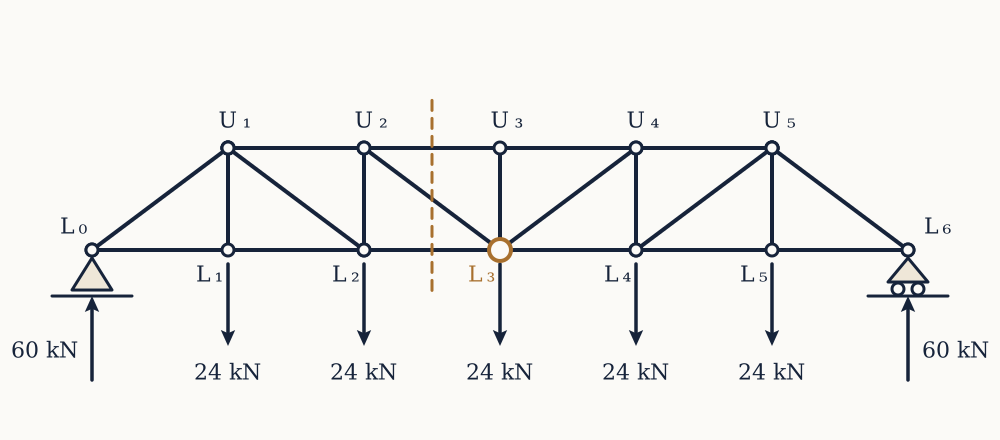
Counting anticlockwise as positive, the reaction at is m to the left of and contributes kN m. The loads at and are m and m to the left and contribute and kN m. The top chord force acts horizontally at m above the moment point, contributing if it is tensile. Everything else in the cut passes through and drops out. So , giving kN: the top chord carries kN of compression, which is what a top chord should do.
Now you. Using the same truss and the same cut, find the force in the bottom chord by taking moments about at .
Answer
The diagonal and the top chord both pass through , so only the bottom chord force survives from the cut. The reaction contributes kN m, the load at contributes kN m, and the load at sits directly below and contributes nothing. A tensile bottom chord force acting m below the moment point contributes . So and kN, tension.
Solving the whole truss gives a pattern worth reading. The bottom chord runs , , , , , kN in tension from one end to the other, and the top chord runs , , , kN in compression. Both track the bending moment of an equivalent solid beam, divided by the depth of the truss: the chords are doing the beam's bending and the web members are doing its shear. The end diagonals carry kN of compression and the diagonals nearer midspan only and kN, because shear is largest at the supports and smallest in the middle. The vertical at midspan carries exactly zero, since the two diagonals meeting at each contribute kN of upward pull, together taking the whole kN load at that joint.
Counting members and joints
Before analysing anything, count. Each joint gives two equations in a plane, so a truss with joints supplies equations. The unknowns are the member forces plus the reaction components. Then
is the condition for a statically determinate truss, marks a mechanism with too few bars, and marks an indeterminate truss with more bars than statics can sort out.
Example. Check the six-panel truss above.
Its joints are to and to , so . Its members are six bottom chords, four top chords, five verticals, two end diagonals and four interior diagonals, so . A pin and a roller give . Then and : determinate, as the section calculations assumed.
Now you. A planar truss has joints, members, a pin at one support and a roller at the other. Classify it.
Answer
while . There is one member more than statics can handle, so the truss is statically indeterminate to the first degree.
As in the previous lesson, the count is necessary and not sufficient. A truss can satisfy and still be a mechanism if the bars are arranged badly, with a redundant bar in one panel paying for a missing one somewhere else. The count catches the common mistakes and the geometry has to be looked at anyway.
What the truss analysis still does not tell you
At the end of all this every member has a number attached: kN of tension in one bottom chord, kN of compression in an end diagonal. Nothing yet says whether any of them survives.
Two gaps remain. The first is that a force is not a verdict: kN would snap a bicycle spoke and would barely register in a bridge chord, so the force has to be compared against the size of the member. That comparison is stress, two lessons away. The second is that tension and compression are not mirror images. A slender bar in compression can fail by bowing sideways at a load far below anything the material would object to, which is the subject of the buckling lesson and the reason truss compression members are stocky while ties can be thin cables.
Before either, there is the more common structural element that a truss was invented to replace over short spans. A beam takes its load anywhere along its length rather than only at joints, so the force it carries varies from point to point, and describing that variation is the next step.