Knowing that a beam pushes back on its supports with 8 kN and 4 kN says nothing about the beam. A truss member was described by one number because its ends were pins, but a beam is loaded along its length, so what it carries at one point is not what it carries at another, and the failure will happen wherever the worst of it is.
Cutting the beam open
Take a beam in equilibrium, imagine a plane slicing through it at a distance from the left end, and throw the right-hand part away. The left part is not in equilibrium on its own, because the material that was removed used to push on it. Restore that push as a set of forces on the cut face, and the left part is a legitimate free body again.
In a plane the cut face can carry exactly three things, because three is what equilibrium can demand. There is a force along the beam's axis, the axial force . There is a force across the axis, the shear force . And there is a couple in the plane, the bending moment . Everything a beam does internally is those three numbers as functions of position.
By Newton's third law the right-hand part carries the mirror image of the same three actions on its own face, so either side may be used and they must agree. Choosing the side with fewer forces on it is pure convenience, and using the other side as a check is free.
Beams loaded only across their axis have throughout, which is why a first course concentrates on and . Columns, arches and any beam carrying a diagonal cable have all three at once, and the lesson on combined stress puts them back together.
A sign convention that has to be fixed
Shear and moment have no natural sign, so a convention is imposed and then obeyed. The standard one is written in terms of what the internal action does to a short element rather than which direction an arrow points, which is what makes it work from either side of the cut.
The bending moment is positive when it sags: when it makes the beam concave upwards, stretching the bottom fibres and compressing the top ones. Negative bending is hogging, and it happens over the supports of a continuous beam and along any cantilever. The distinction is not cosmetic. Reinforced concrete needs its steel where the tension is, so getting the sign wrong puts the reinforcement in the compression face, which is a real and repeated construction failure.
The shear force is positive when the left-hand part tends to slide upwards relative to the right-hand part. Equivalently, at a cut, the positive shear on a left segment points downwards on the exposed face.
With that fixed, the recipe is mechanical. To find and at a section, take the free body to one side, sum the transverse forces on it to get , and take moments about the cut to get .
The two standard cases
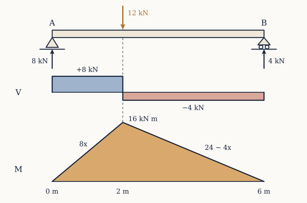
Example. A beam spans m between a pin at and a roller at , carrying a point load of kN at m from . Find the shear and bending moment everywhere.
The reactions were found in an earlier lesson: kN and kN. For , the left free body carries only , so kN, constant, and , rising linearly to kN m at the load. For , the left free body carries and the load, so kN, again constant, and , falling linearly to zero at . Checking from the right at the load point, kN m, which agrees.
The shape is worth memorising: under point loads the shear diagram is a set of steps and the moment diagram is a set of straight lines with a peak under the load.
Now you. The same arrangement spans m with a kN load at m from . Find the shear either side of the load and the maximum bending moment.
Answer
The reactions are kN and kN. The shear is kN to the left of the load and kN to its right. The maximum moment is under the load, kN m, which the right-hand free body confirms as kN m.
The other case that appears everywhere is a uniformly distributed load over the whole span , which is what a beam's own weight and most floor loads look like. Symmetry gives . At a section from the left, the free body carries the reaction and the load that sits on it, acting at . So
The shear falls linearly from to and crosses zero at midspan. The moment is a parabola, zero at both ends, peaking at with
That result is used more than any other in structural engineering, and it is worth carrying the derivation rather than the formula, because the same three lines give the answer for a partial load or an unsymmetrical one where the formula does not apply.
Example. A floor beam spans m and carries kN m⁻¹ over its whole length. Find the end shear and the maximum moment.
at the supports is kN. The maximum moment is kN m at midspan.
Now you. A beam spans m under kN m⁻¹. Find the same two quantities.
Answer
kN at each support, and kN m at midspan.
The two derivatives
Rather than cutting the beam at every position, take an element of length carrying a distributed load downwards. Shear and moment act on its left face, and and on its right.
Vertical equilibrium of the element gives , so
Moment equilibrium about the right face gives . The last term carries and vanishes in the limit, leaving
These two turn diagram drawing into calculus. The slope of the shear diagram is minus the intensity of loading, so under no load the shear is constant, under a uniform load it is a straight slope, and at a point load it jumps by the size of the load. The slope of the moment diagram is the shear, so where the shear is constant the moment is linear, where the shear is linear the moment is parabolic, and where the shear passes through zero the moment is stationary.
That last consequence is the working tool: the maximum bending moment occurs where the shear force is zero, or at a point where the shear jumps through zero. Integrating instead of differentiating gives the other half, that the change in moment between two sections equals the area under the shear diagram between them, which is often the fastest way to get a number without writing an equation at all.
A concentrated couple applied to the beam, from a bracket or an offset column, produces a step in the moment diagram and no change at all in the shear, which the two relations predict correctly and intuition usually does not.
Example. A beam spans m between a pin at and a roller at , carrying kN m⁻¹ over its whole length plus a kN point load m from . Where is the maximum moment, and how large is it?
The reactions, found earlier, are kN and kN. To the left of the point load the shear is , which reaches kN just before and never reaches zero. At the load it drops by to kN. So the shear passes through zero exactly at the point load, and that is where the moment peaks:
Now you. For the same beam, what is the bending moment at midspan, m?
Answer
The point load is to the right of the cut, so the left free body carries only the reaction and kN of distributed load acting at m. So kN m, less than the peak of kN m under the load.
Cantilevers and overhangs
A cantilever is the case where all the bending is hogging. For a cantilever of length built in at the left with a point load at the free end, cutting anywhere gives and , so the moment is largest in magnitude at the support, , and zero at the tip. Under a uniform load the root moment is , four times the midspan moment of a simply supported beam of the same span and load. That factor is why cantilevers are expensive and why a balcony is short.
Overhangs mix the two and produce the one result that surprises people.
Example. A beam has a pin at at and a roller at at m, and continues as an overhang to a free end at m, where a kN load hangs. Find the reactions and the moment at .
Moments about : , so kN. Vertical balance gives kN. The reaction at is negative, which means the beam is trying to lift off its support there and must be able to hold it down. Cutting just left of and using the short right-hand segment, kN m: hogging over the support, as an overhang always is. Between and the moment runs linearly from zero to kN m, so this beam is in hogging over its entire length.
Now you. The same layout has the roller at m, the free end at m, and a kN load at the tip. Find and the moment at the roller.
Answer
Moments about : , so kN and kN, again an uplift. The moment at the roller is kN m.
Uplift is a genuine design case rather than an arithmetic curiosity. A crane counterweight, a cantilevered canopy, and a light roof under wind suction all produce it, and a support detailed to resist only downward force will simply open up.
From diagram to verdict
At this point a beam can be described completely: shear and moment at every section, from the loads and the geometry alone, with no reference to what the beam is made of or how big it is. That independence is exactly why the diagrams are worth drawing first. For a determinate structure the internal forces are settled by statics, so the same diagram serves a timber joist and a steel girder.
It is also why the diagrams cannot decide anything. A moment of kN m is comfortable for a rolled steel section mm deep and hopeless for a mm square timber. To convert an internal action into a verdict, the action has to be spread over the material that carries it, which turns kilonewtons into a quantity that can be compared against a laboratory test on a small sample. That quantity is stress, and it is next.