Sign in

Libre University uses your GitHub account. Signing in is only needed to sit a final test, so the score is kept on your profile.

Theory of Circuits

How electricity works, from the charge and fields of physics to the current, voltage and resistance of a real circuit, through capacitors and inductors, and on to alternating current, impedance and resonance.

Charge and the electric field

Electricity is not a substance that flows into a wire from outside. It is the collective behaviour of a property that matter already carries everywhere, all the time, called charge. A circuit is charge being pushed around a loop, resistance is charge being slowed, a capacitor is charge being stored, and alternating current is charge being rocked back and forth. Before any of that can make sense, the property itself has to be pinned down, and it turns out to have just a few rules, from which the whole subject is built.

Two kinds, and the sign convention

Charge comes in two kinds, and the two are opposite in a strict sense: bring like kinds together and they push apart, bring opposite kinds together and they pull in. Benjamin Franklin named them positive and negative before anyone knew what carried them, and the names stuck, which is why the particle we now know does most of the moving in a wire, the electron, is negative. That was a coin flip Franklin lost, and it leaves the field with a permanent awkwardness: the thing that physically flows in a metal, the electron, moves opposite to the direction we call the current. The subject lives with the confusion by keeping two ideas apart, and this lesson keeps them apart too.

Charge is measured in coulombs, symbol C, and the coulomb is a large unit: the charge on a single electron is only 1.6×10⁻¹⁹ C, so one coulomb is the combined charge of about six billion billion electrons. Two more facts complete the rules. Charge is quantised, always a whole-number multiple of that electron charge, never a fraction of it. And charge is conserved: it is never created or destroyed, only moved, so any charge that leaves one place has gone to another. Conservation is not a detail. It is the reason current is the same all the way around a simple loop, a fact the whole of circuit analysis leans on.

Coulomb's law, the force between charges

Two charges exert a force on each other, and its size follows a law with the same shape as gravity's. The force between charges q1 and q2 separated by a distance r is

F=kq1q2r2

where k=8.99×10⁹ in units of newton metres squared per coulomb squared. The force falls off as the square of the distance, so doubling the separation quarters the force, and it grows with the product of the charges. Its direction is along the line joining them, a push for like charges and a pull for opposite ones, which the sign of the product q1q2 encodes automatically. This inverse-square law is the whole of electrostatics in one line, and every richer idea in the subject is a way of applying it to more charges than two.

Example. Two small spheres each carry +2×10⁻⁶ C and sit 5 cm apart. What is the force between them, and which way does it point?

F=8.99×109×(2×10-6)2/(0.05)2=8.99×109×4×10-12/0.0025=14.4 N, and since both are positive the force is a push, driving the spheres apart. Fourteen newtons from two specks of charge is a hint of how strong the electric force is compared with gravity.

Now you. The spheres are moved to 10 cm apart, charges unchanged. What is the new force?

Answer

Doubling the distance quarters the force, so F=14.4/4=3.6 N, still a push.

The field, action carried through space

Coulomb's law gives the force between two charges, but it is awkward to think of every charge reaching out and touching every other one directly. The more powerful idea, and the one the rest of the subject uses, is that a charge fills the space around it with an electric field, and any other charge placed in that space feels a force from the local field rather than from the distant charge. The field at a point is the force per unit charge that a small positive test charge would feel there:

E=Fq

measured in newtons per coulomb, or equivalently volts per metre once the next lesson introduces the volt. The field points away from positive charge and toward negative charge, and its strength falls off with distance just as the force does. The value of the field idea is that it lets a charge respond to what is happening right where it sits, with no need to know where the charges that made the field are. In a wire, the field is what pushes the charges along, set up by the battery at the ends, and every charge in the wire feels the local push and moves, which is the beginning of a current.

Conductors and insulators

Matter divides, for this subject, into two camps by what its charges are free to do. In a conductor, above all a metal, some electrons are not bound to any one atom but are free to roam through the whole material, so an applied field sets them drifting and charge flows. In an insulator, glass, plastic, dry air, every electron is held tightly to its atom, so a field shifts them only slightly and no sustained flow occurs. This single difference is why a circuit is built of metal wires wrapped in plastic: the metal offers the charge a road, and the plastic walls it in so the charge goes where it is wanted and not through the person holding it. The free electrons in a metal are the movable charge of every lesson that follows, and the field that pushes them, set up by a source with the strange power to keep pushing, is the subject of the next lesson: what a voltage actually is.
Voltage, the pressure that drives charge

The last lesson left charge sitting in a field, pushed by a force. Force is a clumsy thing to track around a circuit, because it points in a direction and changes from place to place. Energy is far easier, because it is a single number, and the quantity a circuit is really organised around is not force but energy per unit charge, which is called voltage. Voltage is the most used word in the subject and the most often misunderstood, so it is worth building from the ground up, because once it is clear the rest of the theory falls into place around it.

Potential energy, then energy per charge

Lift a rock and you store gravitational potential energy in it, energy that gravity will give back as motion if you let the rock fall. Push a positive charge toward another positive charge, against their repulsion, and you store electric potential energy in exactly the same way, energy the field will give back if you release the charge. So far this is Coulomb's law seen through energy rather than force. The step that makes it useful for circuits is to divide out the charge. The electric potential at a point is the potential energy a charge would have there, per unit of its charge:

V=Uq

Dividing by the charge strips away how much charge you happen to be carrying and leaves a property of the location alone, the way the height of a hill is a property of the hill and not of the particular rock you carry up it. Potential is measured in volts, and one volt is one joule of energy per coulomb of charge. A point at 5 V will give up 5 joules to every coulomb that falls from it to zero.

Only differences matter

Potential, like height, has no absolute zero that nature cares about. What drives anything is a difference in it, a potential difference, and this is what everyday language calls a voltage across something. A 9 V battery does not mean its terminals hold some absolute nine volts; it means one terminal sits nine volts higher than the other, so each coulomb that travels from the high terminal to the low one through a circuit gives up nine joules along the way. Because only differences matter, one point in any circuit is chosen as the reference and called ground or zero volts, and every other voltage is quoted relative to it. Choosing where ground sits is free and changes no current, exactly as choosing to measure heights from the sea or from the valley floor changes no waterfall.

The gravitational picture is worth holding onto because it is not merely an analogy but the same mathematics with a different force. Voltage is electrical height. A battery is a pump that lifts charge to a high potential. A wire is level ground the charge coasts along. A resistor is a slope the charge tumbles down, giving up energy as it goes. Charge flows downhill in voltage exactly as water flows downhill in height, and a circuit that goes nowhere, with both ends at the same potential, drives no current for the same reason a lake with a level surface has no stream.

Example. A battery raises 3 coulombs of charge through a potential difference of 12 V. How much energy does it give them?

Energy is charge times potential difference, U=qV=3×12=36 J. Each coulomb gains 12 J, and three coulombs gain 36 J, which the circuit will spend as the charge flows back down to the low terminal.

Now you. A 1.5 V cell pushes 4 coulombs through a torch. How much energy does it deliver to them?

Answer

U=qV=4×1.5=6 J.

Electromotive force, the source that keeps lifting

Charge flowing downhill in voltage loses energy, so a circuit that only ran downhill would stop the moment its charge reached the bottom, like a waterfall that drains its lake. Something has to lift the charge back up, and that something is a source, a battery or a generator, whose defining ability is to push charge from low potential to high, against the field, by spending some other kind of energy. A battery spends chemical energy; a generator spends mechanical energy. The measure of how hard a source lifts is its electromotive force, or EMF, which despite the name is not a force but a voltage, the energy per coulomb the source adds. The EMF is the height of the pump. A real source also has a small internal resistance that eats a little of that lift as current flows, which is why a battery's terminal voltage sags under load, an effect met already in the quadcopter's power system and explained fully a few lessons on.

Why voltage is where circuits begin

The reason voltage, not force or field, is the natural language of circuits is that a circuit is an energy machine. A source lifts charge to a high potential, the charge flows around the loop through wires and components, and at each component it gives up some of its energy per coulomb, its share of the voltage, doing work: heating a resistor, lighting a lamp, spinning a motor. Add up the voltage the charge gains at the source and the voltages it loses around the loop and they must balance, because the charge returns to where it started with the energy it started with, a bookkeeping rule that becomes one of the two great laws of circuit analysis a few lessons from here. Everything from here is charge moving through voltage differences, and the first thing to quantify is the moving itself: how much charge passes, how fast, which is the current of the next lesson.

Electric current, charge in motion

Voltage is the cause and current is the effect. Once a source sets up a potential difference across a conductor, the free charges in it start to move, and the measure of that movement is the current. It is one of the two quantities a meter reads directly and one of the two that every circuit law is written in, so a clear definition earns its keep. Current answers a simple question: how much charge flows past a point each second.

The definition

Pick any cross-section of a wire and count the charge that crosses it. The current is the rate of that crossing:

I=ΔQΔt

the charge ΔQ that passes in a time Δt, divided by the time. Its unit is the ampere, symbol A, and one ampere is one coulomb per second. A current of 2 A means two coulombs, more than ten billion billion electrons, stream past every second. The ampere is one of the base units from which the rest of the electrical units are built, which is a historical accident worth noting: current, being the easiest thing to measure with a force between two wires, was made fundamental, and the coulomb was then defined as an ampere-second rather than the other way around.

Current has a direction, and here the convention set two lessons ago returns to bite. Conventional current is defined as the direction positive charge would move, from high potential to low, from the plus terminal of a battery around the circuit to the minus. In a metal the actual carriers are electrons, which move the opposite way, but every equation in this course uses the conventional direction, and the two only need to be reconciled when the physics of the metal itself is in question. For solving circuits, current flows from plus to minus through the external circuit, and that is all that is needed.

Drift is slow, the signal is fast

A surprise lurks in how fast the charges actually move. Inside a metal the free electrons are already flying about at enormous speeds in random directions, but with no field their motion averages to nothing. Switch on a field and a slow, steady bias is added to the chaos, a drift velocity that is astonishingly small: in a typical wire carrying a normal current, the electrons drift along at well under a millimetre per second, slower than a snail. Yet a lamp lights the instant its switch is thrown, metres of wire away. The resolution is that the wire is already full of charge everywhere, so the field, which travels through the wire at nearly the speed of light, starts all of them moving almost at once. Pushing the near end of a pipe already full of water makes water leave the far end immediately, though no single drop crossed the pipe. The electrons crawl; the push that marshals them races. It is the push, not the crawl, that lights the lamp.

Example. A current of 0.5 A flows through a wire for 2 minutes. How much charge passes, and roughly how many electrons is that?

The time is 120 s, so ΔQ=IΔt=0.5×120=60 C. Dividing by the electron charge, 60/(1.6×10-19)=3.75×1020 electrons. A modest current for two minutes moves a number of electrons with twenty zeros after it, which is why charge is tracked in coulombs and not by counting.

Now you. A phone charger delivers 1.2 A for 90 minutes. How many coulombs of charge does it move?

Answer

ΔQ=IΔt=1.2×(90×60)=1.2×5400=6480 C.

Current is the same all the way along

A single unbranched path carries the same current at every point along it, and the reason is conservation of charge from the first lesson. Charge is never created or lost in a wire, so whatever flows into one end of a resistor in a series chain flows out the other end and on into the next component, unchanged. This sounds obvious and is constantly forgotten. A resistor does not use up current; it uses up voltage, dropping the charge to a lower potential while passing every coulomb through. The lamp at the end of a chain draws exactly the current that left the battery, not some remainder. Where a wire branches, the current splits, and where branches rejoin, it adds back, in such a way that as much flows out of any junction as flows in. That balance at a junction is one of the two laws that solve every circuit, met in full a few lessons on, and it is nothing more than the statement that charge does not pile up or vanish.

Measuring it, and the danger of the ammeter

Because current is a flow through a point, the instrument that reads it, an ammeter, must be placed in the path so that the current it measures runs through it, in series with the component of interest. This is the opposite of the voltmeter of the last lesson, which is placed across a component to read the potential difference between its ends. The distinction is a common beginner's trap with a costly failure mode. An ammeter is built to have almost no resistance, so that inserting it barely disturbs the circuit, which means connecting one directly across a battery, as a voltmeter would be connected, offers the battery a near short circuit through the meter and can destroy it. Current is measured through, voltage across, and the two are not interchangeable. With charge, voltage and current now defined, the stage is set for the single relation that ties current to voltage in most materials, and the property that stands between them, which is resistance.

Resistance and Ohm's law

A voltage pushes and a current flows, but how much current flows for a given push depends on what the charge is being pushed through. A thick copper bar barely resists the flow; a thin coil of nichrome wire resists it strongly and glows red as a result. The property that decides how much current a given voltage produces is resistance, and the relation between the two is so simple and so central that most of practical circuit work is applying it.

Ohm's law

For a large class of materials, the current through a component is directly proportional to the voltage across it. Double the voltage and the current doubles. The constant of proportionality is the resistance, and the relation is Ohm's law:

V=IR

with V the voltage across the component in volts, I the current through it in amperes, and R the resistance in ohms, symbol Ω. One ohm is one volt per ampere: a resistance of one ohm passes one ampere when one volt is placed across it. Rearranged, the law says I=V/R, which reads more directly as cause and effect: a fixed voltage drives a current that shrinks as the resistance grows. A component that obeys this proportionality is called ohmic, and a plain resistor is the deliberate embodiment of one, a part made to have a known, steady resistance and nothing else.

Not everything is ohmic, and it is worth saying so early to keep the law in its place. A filament lamp grows more resistive as it heats, so its current rises less than proportionally with voltage. A diode passes current one way and blocks it the other, obeying no such proportionality at all. Ohm's law is a superb description of metals and resistors at steady temperature, not a law of nature that everything must follow, and the skill is knowing which components it describes.

Example. A 220 ohm resistor has 5 V across it. What current flows through it?

I=V/R=5/220=0.0227 A, or 22.7 mA. Currents in small electronics are usually milliamps, thousandths of an ampere, which is why the milliamp is the everyday unit on a bench.

Now you. What voltage appears across a 1000 ohm resistor carrying 12 mA?

Answer

V=IR=0.012×1000=12 V.

What resistance is made of

Resistance is not magic; it is the charge colliding with the material as it drifts. The free electrons pushed by the field do not sail cleanly through a metal but bump repeatedly against the vibrating atoms of the lattice, losing energy to them at each collision, and that constant obstruction is resistance. The energy lost heats the material, which is why a resistor warms and a filament glows, and it is the mechanism behind the power dissipation of the next lesson. Because the atoms vibrate more when hot, a metal collides with its electrons more often when heated and so grows more resistive with temperature, which is the filament lamp's behaviour explained.

The resistance of a particular piece of wire follows a clean geometric rule. It rises with the length, because a longer path means more collisions, and falls with the cross-sectional area, because a fatter conductor offers more lanes for the charge to travel in parallel:

R=ρLA

Here L is the length, A the cross-sectional area, and ρ the resistivity, a property of the material itself that says how resistive a unit cube of it is. Copper has a very low resistivity, which is why wires are made of it; nichrome has a high one, which is why heating elements are made of it. The formula is why long thin wires drop noticeable voltage while short fat ones do not, the fact that sized the battery leads in the quadcopter's power system, and it is the bridge from a material's nature to a component's behaviour.

Example. A copper wire 10 m long has a resistance of 0.5 ohms. A second copper wire of the same thickness is 30 m long. What is its resistance?

Resistance is proportional to length at fixed thickness, so tripling the length triples the resistance: 0.5×3=1.5 ohms. The material and thickness are unchanged, so only the length ratio matters.

Now you. A wire is replaced by one of the same material and length but twice the cross-sectional area. What happens to its resistance?

Answer

Resistance is inversely proportional to area, so doubling the area halves the resistance.

Conductance, the other way to say it

Sometimes it is more natural to speak of how easily current flows rather than how strongly it is opposed, and that is conductance, simply the reciprocal of resistance, G=1/R, measured in siemens. A high conductance is a low resistance. The idea earns its place when components are combined in parallel a couple of lessons on, where conductances add as neatly as resistances add in series, but it is worth meeting now as a reminder that resistance and conductance are two views of one fact: the relationship between the push and the flow. That relationship, V=IR, together with the two conservation laws still to come, is enough to solve any resistive circuit ever drawn, and the next lesson turns to what the resistance is doing with the energy it takes from the charge.

Power and energy in a circuit

A circuit exists to move energy from a source to somewhere it is wanted, and the rate of that transfer is power. Every component either delivers power, as a battery does, or consumes it, as a resistor, lamp or motor does, and the arithmetic of power is short and governs an enormous amount of practical design, from why a phone charger is warm to why a power line runs at hundreds of thousands of volts.

Power is voltage times current

Recall two definitions. Voltage is energy per unit charge, and current is charge per unit time. Multiply them and the charge cancels, leaving energy per unit time, which is power:

P=VI

with power in watts, symbol W, where one watt is one joule per second. A component with 12 V across it carrying 2 A is handling 12×2=24 W, turning twenty-four joules into some other form every second. The formula is completely general: it holds for a resistor, a motor, a battery, anything, because it is just the two definitions multiplied. Where the energy goes depends on the component. In a resistor it all becomes heat. In a motor most becomes motion. In a battery being charged it becomes stored chemistry. The watt does not care; it only counts the rate.

The three faces of resistor power

For a resistor, Ohm's law lets power be written three equivalent ways, and choosing the right one is half the skill. Starting from P=VI and substituting V=IR or I=V/R gives

P=VI=I2R=V2R

All three give the same number for a given resistor; they differ in which two quantities you happen to know. The middle form, P=I2R, is the one to burn into memory, because it carries the subject's recurring warning. Power lost as heat in a resistance grows with the square of the current. Double the current through a wire and you quadruple the heat it makes. This is why current, not voltage, is what melts wires and burns out the ESCs of the drone course, and why the fat leads on a high-current build were fat. It is also the argument for high-voltage power transmission: to deliver a fixed power a grid can use high voltage and low current or low voltage and high current, and since the loss in the lines is I2R, sending it at high voltage and low current wastes far less in heating the cables. The same power, chosen as low current, arrives nearly intact.

Example. A resistor carries 0.5 A and has 6 V across it. What power does it dissipate, and check it a second way given its resistance.

P=VI=6×0.5=3 W. Its resistance is R=V/I=6/0.5=12 ohms, so P=I2R=0.25×12=3 W, agreeing. The three forms are a built-in check on your arithmetic.

Now you. A 100 ohm resistor has 10 V across it. Use the form that needs only those two numbers to find the power.

Answer

P=V2/R=100/100=1 W.

From power to energy

Power is a rate; energy is the total delivered, power multiplied by the time it flows:

E=Pt

in joules when power is in watts and time in seconds. A 3 W resistor left on for 10 s dissipates 30 J. Because the joule is a small unit for household amounts of energy, the electricity meter uses the kilowatt-hour, the energy of one kilowatt flowing for one hour, which is 1000×3600=3.6 million joules. A 2 kW heater run for three hours uses 6 kWh, and that is the number a bill charges for. Energy, not power, is what is bought and paid for, and the distinction between the rate and the total is one that trips people constantly: a powerful device used briefly can cost less than a weak one left on all day.

Example. A 60 W lamp is left on for 5 hours. How much energy does it use, in kilowatt-hours?

0.060 kW times 5 hours is 0.30 kWh. In joules that is 60×(5×3600)=1.08 million J, which is why the kilowatt-hour exists: 0.30 is a friendlier number than a million.

Now you. A 2000 W kettle runs for 4 minutes. How much energy does it use, in kilowatt-hours?

Answer

Four minutes is 4/60=0.0667 h, so 2.0×0.0667=0.133 kWh.

Efficiency, and where the rest goes

No real device turns all the power it draws into what you want. A motor draws electrical power and delivers mechanical power, but some is lost to heat in its resistance and friction, and the ratio of useful output to total input is its efficiency. A device that draws 100 W and delivers 85 W of useful output is 85 per cent efficient, and the missing 15 W has become heat, which is why hard-working electronics need cooling. Efficiency is where the earlier lessons connect: the I2R loss in every wire and winding is the leak, and a well-designed system is one that keeps current low where it can, spends voltage deliberately, and treats every watt of heat as a watt it failed to use. With power and energy in hand, the circuit can now be more than a single loop, and the next lesson gives the two laws that handle any arrangement of components, however tangled.

Series, parallel, and Kirchhoff's laws

A single resistor across a battery is solved by Ohm's law alone. Real circuits have many components wired in tangles, and to handle them the subject rests on two laws so simple they can feel like restatements of the obvious, which is exactly their strength. They are Kirchhoff's laws, and each is a conservation principle already met, now sharpened into a tool. Together with Ohm's law they are complete: no resistive circuit exists that these three cannot solve.

The current law, charge is conserved at a junction

A junction is any point where wires meet and current can divide or combine. Kirchhoff's current law states that the total current flowing into a junction equals the total current flowing out. Nothing accumulates there, because charge is conserved and a junction is not a reservoir. If 3 A arrive along one wire and split into two, the two must carry 3 A between them, in whatever division the rest of the circuit dictates. Written as a balance, the currents in equal the currents out at every junction, and that is the law that governs how current shares itself among parallel paths.

The voltage law, energy is conserved around a loop

A loop is any closed path through the circuit that returns to where it began. Kirchhoff's voltage law states that around any loop the voltage rises and the voltage drops cancel exactly, summing to zero. This is energy conservation seen per unit charge: a charge carried once around a loop returns to its starting potential, so whatever energy it gained at sources it must have given up at components, with nothing left over. The battery lifts each coulomb by its EMF, and the resistors around the loop drop it back down by their share of that voltage, and the shares add up to the lift. This law is what lets a source voltage be split among the components in series with it.

Series, resistances add

Components are in series when they lie on a single path so the same current flows through all of them, one after another. Because the same current runs through each, and the voltage law says their voltage drops add up to the source voltage, their resistances simply add:

Rseries=R1+R2+R3+

Three resistors of 100, 220 and 330 ohms in series behave as one 650 ohm resistor. The current is the same everywhere along the chain, and the source voltage divides among them in proportion to their resistances, since the bigger resistor drops more voltage for the same current. This last fact is the voltage divider, one of the most used patterns in electronics: two resistors in series split a voltage in the ratio of their values, so that the voltage across the second is the source voltage times R2/(R1+R2).

Example. A 9 V battery is across two series resistors, 1000 ohms and 2000 ohms. What current flows, and what is the voltage across the 2000 ohm resistor?

The total resistance is 1000+2000=3000 ohms, so the current is I=9/3000=3 mA, the same through both. The voltage across the 2000 ohm resistor is IR=0.003×2000=6 V, which is also 9×2000/3000=6 V by the divider, agreeing.

Now you. Two resistors, 470 ohms and 330 ohms, are in series across 8 V. What is the current?

Answer

Total resistance 470+330=800 ohms, so I=8/800=0.01 A, or 10 mA.

Parallel, conductances add

Components are in parallel when they are connected across the same two points, so the same voltage sits across all of them and the current divides among them. Here it is the conductances, the reciprocals of resistance, that add, which for resistance itself gives the reciprocal rule:

1Rparallel=1R1+1R2+

The result is always smaller than the smallest resistor in the group, because adding another path can only make it easier for current to flow, never harder. Two equal resistors in parallel give half the resistance; a 100 ohm and a 100 ohm in parallel act as 50 ohms. The reason conductance is the natural quantity here is exactly this: another lane in parallel adds its ease of flow to the total, so the eases add while the resistances do the awkward reciprocal dance. The current law then splits the total current among the branches in proportion to their conductances, the current divider, so the lower-resistance branch takes the larger share.

Example. A 100 ohm and a 100 ohm resistor are in parallel across 5 V. What is the combined resistance, and the total current from the source?

Two equal resistors in parallel halve the resistance, giving 50 ohms. The total current is I=5/50=0.1 A, which splits into 0.05 A through each branch, since equal resistances share the current equally.

Now you. A 200 ohm and a 300 ohm resistor are in parallel. What is their combined resistance?

Answer

1/R=1/200+1/300=0.005+0.00333=0.00833, so R=120 ohms, smaller than either.

Reducing a network

The power of these rules is that any ladder of resistors, however complicated, can be collapsed step by step. Find a group that is clearly series or clearly parallel, replace it with its single equivalent, and the circuit gets simpler; repeat, and a page of resistors becomes one number, from which the source current follows by Ohm's law. Working back outward then recovers the voltage across and current through every original component. This reduce-and-expand method handles the great majority of circuits a builder meets. A minority are wired so that no two components are cleanly in series or parallel, a bridge being the classic case, and those need the more systematic machinery of the next lesson. But the two laws are the whole foundation, and they are worth stating once more in their plainest form: charge does not pile up at a junction, and energy does not appear or vanish around a loop.

Node voltages and equivalent sources

The reduce-and-expand method of the last lesson fails on circuits that have no clean series or parallel groups to collapse, the bridge network being the standard example, where every resistor is entangled with every other. Such circuits are not harder in principle; they only need a method that does not rely on spotting simple groupings. The method that always works is to make the unknowns the voltages at the circuit's nodes and to enforce Kirchhoff's current law at each one, turning the circuit into a small set of equations. Alongside it sits a second idea of great practical value: that any two-terminal box of sources and resistors, however complex inside, behaves from outside exactly like one source and one resistor.

Node analysis

A node is a point of the circuit at a single voltage, all the junctions connected by plain wire counting as one node. Pick one node as the reference, ground, and call it zero volts, and let the voltage at every other node be an unknown. At each unknown node, Kirchhoff's current law says the currents leaving through the connected resistors sum to zero, and each such current is written by Ohm's law as the voltage difference across the resistor divided by its resistance. Writing that balance at every node gives one equation per unknown node, and solving the set gives every node voltage at once. From the node voltages, every branch current and component voltage follows immediately. The virtue of the method is that it never needs to recognise a series or parallel group; it grinds any circuit, tangled or not, into linear equations that always have a solution.

Example. A node sits at unknown voltage V. It connects through 1000 ohms to a 10 V supply, through 2000 ohms to ground, and through 2000 ohms to ground again. Find V by balancing the currents.

The current law says the current in from the supply equals the current out to ground: (10-V)/1000=V/2000+V/2000=V/1000. So 10-V=V, giving V=5 V. One equation, one unknown, and the node voltage drops out; every branch current then follows by Ohm's law.

Now you. A node at voltage V connects through 1000 ohms to a 12 V supply and through 1000 ohms to ground, with nothing else attached. What is V?

Answer

(12-V)/1000=V/1000, so 12-V=V and V=6 V. This is the voltage divider again, recovered from the node balance.

Thevenin's equivalent, a box seen from two terminals

Often only two terminals of a complicated circuit matter, the two where something will be connected, and everything behind them is detail. Thevenin's theorem makes that detail collapse: any network of sources and resistors, viewed from two terminals, behaves exactly like a single voltage source in series with a single resistance. The source, the Thevenin voltage, is the voltage that appears across the two terminals with nothing connected, the open-circuit voltage. The resistance, the Thevenin resistance, is the resistance seen looking back into the terminals with the sources turned off, voltage sources replaced by wires. Whatever is then attached to the terminals cannot tell the real network from this simple pair, because they deliver the same voltage and current for every possible load. The theorem is what lets an engineer treat a whole power supply, or a whole sensor circuit, as one source and one resistance when designing what plugs into it.

Example. A 12 V supply feeds two equal 1000 ohm resistors in series, and the two terminals of interest are across the second resistor. What is the Thevenin equivalent seen there?

With nothing connected, the divider puts half the supply across the second resistor, so the Thevenin voltage is 6 V. Turning off the source, the two 1000 ohm resistors appear in parallel across the terminals, giving a Thevenin resistance of 500 ohms. So the whole thing looks, from those terminals, like a 6 V source behind 500 ohms.

Now you. If instead both resistors were 2000 ohms, what would the Thevenin voltage and resistance across the second one be?

Answer

The divider still gives half, so the Thevenin voltage is 6 V, and the two 2000 ohm resistors in parallel give a Thevenin resistance of 1000 ohms.

Why the equivalent resistance matters

The Thevenin resistance is not a bookkeeping curiosity; it decides how a source behaves under load. A source with a low equivalent resistance holds its voltage nearly steady as more current is drawn, which is what a good power supply does. A source with a high equivalent resistance sags badly when loaded, which is the internal-resistance sag of a tired battery met in the voltage lesson, now named precisely: the battery's Thevenin resistance is its internal resistance, and the terminal voltage falls by the load current times that resistance. It also sets how much power a source can deliver to a load, which is greatest when the load resistance matches the source's equivalent resistance, a result called maximum power transfer that governs everything from loudspeakers to radio antennas. These methods, node voltages for solving and Thevenin equivalents for simplifying, complete the toolkit for steady direct-current circuits. What they cannot yet handle is a circuit whose currents and voltages change with time, and the next lessons add the two components that make that happen: the capacitor, which stores charge, and the inductor, which stores current's magnetism.

Capacitors, storing charge in a field

Every component so far has responded to voltage and current instantly, with no memory of what came before. The capacitor is the first component with a past. It stores charge, and because charge takes time to move in and out, a capacitor makes a circuit's voltages and currents depend on their own history, which is what turns a circuit from a static divider into something that can time, filter and smooth. Its construction is almost absurdly simple, two conductors held close together but not touching, yet from that a great deal follows.

Charge in proportion to voltage

A capacitor is two conducting plates separated by a thin insulating gap. Connect it to a voltage and charge flows onto one plate and off the other, until one plate holds a positive charge and the other an equal negative charge, with the applied voltage across the gap. The plates never touch, so no charge crosses the gap; it simply piles up on the two faces. The amount that piles up is proportional to the voltage applied:

Q=CV

where Q is the charge on each plate, V the voltage across them, and C the capacitance, measured in farads. One farad is one coulomb stored per volt, which is an enormous capacitance; real capacitors are microfarads, millionths, or smaller, and even a microfarad is a substantial part. Capacitance is a property of the geometry: larger plates hold more charge at a given voltage, and a thinner gap holds more still, because the opposite charges on the two plates attract across a smaller distance and pack more densely. Filling the gap with an insulating material, a dielectric, raises the capacitance further, because the material's own charges shift to partly cancel the field and let more charge pile on for the same voltage.

Example. A 10 microfarad capacitor is charged to 5 V. How much charge does it hold?

Q=CV=10×10-6×5=5×10⁻⁵ C, or 50 microcoulombs. Small, but stored and retrievable, which is the point.

Now you. A 100 microfarad capacitor holds 2 millicoulombs of charge. What voltage is across it?

Answer

V=Q/C=2×10-3/(100×10-6)=20 V.

Energy stored in the field

Charging a capacitor takes work, because each additional bit of charge must be pushed onto a plate that already repels it, and that work is stored, ready to be given back. The stored energy is

E=12CV2=12QV

The factor of a half appears because the voltage was not the full V throughout the charging; it climbed from zero as the charge accumulated, so the average voltage the charge was pushed against was half the final value. The energy lives in the electric field in the gap, the same field of the first lesson, now put to work as a store. A charged capacitor is a reservoir of energy that can be released far faster than a battery can, which is why capacitors run a camera flash and smooth the violent current demands the drone's ESCs make on the battery. The battery holds far more energy; the capacitor gives up its smaller store in an instant, and the two roles are different.

Example. How much energy is stored in a 470 microfarad capacitor charged to 16 V?

E=12CV2=0.5×470×10-6×162=0.5×470×10-6×256=0.060 J. Modest, but delivered in a flash it is a large power.

Now you. A 1000 microfarad capacitor is charged to 10 V. How much energy does it store?

Answer

E=0.5×1000×10-6×100=0.05 J.

Blocking the steady, passing the changing

The rule that no charge crosses the gap has a striking consequence for how a capacitor treats different signals. Once a capacitor is charged to a steady voltage, the flow stops: the plates are full for that voltage, and a steady direct voltage drives no lasting current through a capacitor at all. It blocks steady current. But if the applied voltage changes, charge must rush onto or off the plates to match the new voltage, and that rush is a current, so a capacitor passes a changing signal. The faster the voltage changes, the larger the current needed to keep up, a relationship written as

I=CdVdt

the current is the capacitance times the rate of change of voltage. A capacitor is therefore a component that ignores what is constant and responds to what varies, the exact opposite of a plain resistor's indifference to time. This single behaviour, blocking direct current while passing changes, is the seed of filtering, of coupling one stage of a circuit to the next while keeping their steady levels apart, and of the smoothing capacitor that turns a lumpy supply into a steady one by charging on the peaks and discharging into the dips. It also means that a capacitor and a resistor together do something neither can alone: they take time. Put a resistor in the path that charges a capacitor and the charge cannot arrive instantly, because the resistor limits the current, and the voltage climbs on a curve with a definite pace. That pace, the most useful single number in timing circuits, is the subject of the next lesson.

The RC circuit and the time constant

A capacitor alone charges instantly, in principle, because nothing limits the rush of charge. Put a resistor in the path and the picture changes entirely, because the resistor caps the current, so the charge can only trickle on and the capacitor's voltage climbs gradually. This pairing, a resistor and a capacitor in series, is the RC circuit, and it is the simplest circuit that does something over time. Understanding its one curve and its one number explains timers, the smoothing of power supplies, and the filters that separate fast signals from slow ones.

The charging curve

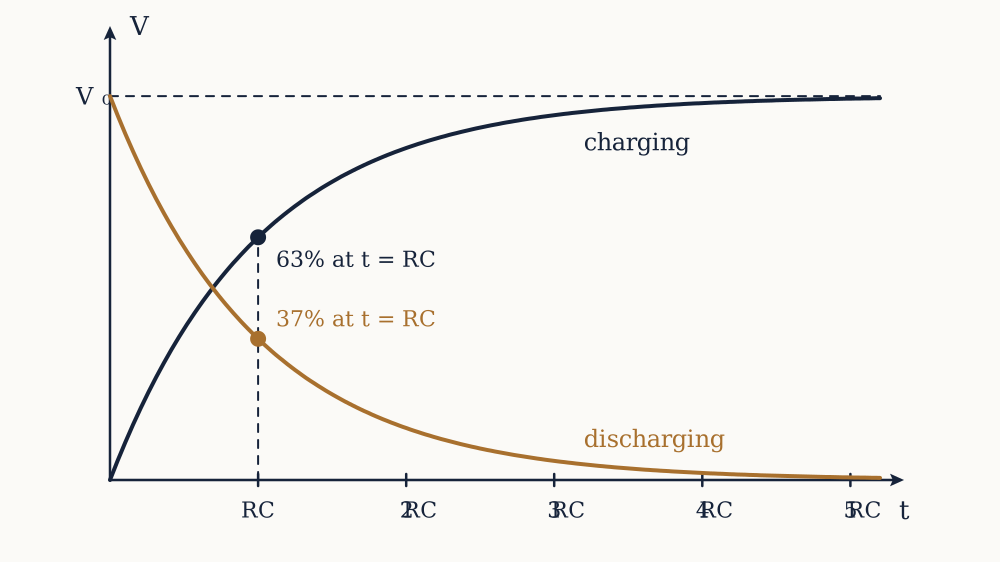
Connect a resistor and capacitor in series to a voltage V0, starting with the capacitor empty. At the first instant the capacitor is at zero volts, so the full source voltage is across the resistor, and by Ohm's law the current is at its largest, V0/R. Charge pours onto the capacitor and its voltage rises, which leaves less voltage across the resistor, so the current falls, so the charging slows. The capacitor fills quickly at first and ever more slowly as it approaches the source voltage, never quite reaching it in the mathematics though it gets there for any practical purpose. The voltage across the capacitor follows

V(t)=V0(1-e-t/RC)

an exponential approach to V0. The discharging case, where a charged capacitor is allowed to empty through a resistor, is the mirror image, an exponential fall:

V(t)=V0e-t/RC

starting at the full voltage and decaying toward zero, fast at first and slowing as it goes. Both curves are governed by the same combination in the exponent, RC, and that combination is the whole story of the circuit's speed.

The time constant

The product RC is called the time constant, written τ, and it has units of seconds, which is worth checking because it is not obvious: an ohm times a farad works out to a second. It is the natural clock of the circuit. After one time constant the charging capacitor has reached 1-e-1=0.63 of the source voltage, about 63 per cent, and the discharging one has fallen to e-1=0.37, about 37 per cent. After about five time constants the process is over to better than one per cent, which is the rule of thumb for how long to wait for a capacitor to settle. The beauty of the time constant is that it collapses the whole behaviour into a single adjustable number: want a slower circuit, use a larger resistor or a larger capacitor; the curve keeps its shape and only its pace changes.

τ=RC

Example. A 10 kilohm resistor charges a 100 microfarad capacitor from a 9 V supply. What is the time constant, and roughly how long until the capacitor is nearly fully charged?

τ=RC=10{,}000×100×10-6=1 second. After one second it reaches about 63 per cent of 9 V, roughly 5.7 V, and after about five seconds it is essentially at 9 V.

Now you. A 1 kilohm resistor discharges a 470 microfarad capacitor. What is the time constant, and what fraction of the starting voltage remains after that one time constant?

Answer

τ=1000×470×10-6=0.47 s, and after one time constant about 37 per cent of the starting voltage remains.

What the circuit is good for

The RC circuit does three jobs that recur everywhere. As a timer, its predictable climb marks out a delay: a circuit that acts when the capacitor voltage crosses a threshold waits a time set by τ, and choosing the resistor and capacitor sets the interval, which is how a great many simple timing circuits are built. As a smoother, a capacitor across a lumpy supply charges on the peaks and discharges into the troughs, and a large enough time constant, slow compared with the lumps, flattens them into a nearly steady voltage, which is how the pulsing output of a power supply becomes usable direct current. As a filter, the circuit treats fast and slow signals differently because the capacitor can follow slow changes but not fast ones: taking the output across the capacitor passes the slow and rejects the fast, a low-pass filter, while taking it across the resistor does the opposite, and the boundary between fast and slow is set once again by the time constant. The same three components, arranged the same way, become a clock, a smoother or a sieve depending only on what is asked of them, all governed by that one product of resistance and capacitance.

Why time entered the subject

The RC circuit is the first place the subject has a memory, and it is worth seeing why. A resistor's voltage depends only on the current through it right now; a capacitor's voltage depends on all the charge that has ever flowed onto it, the whole past summed up. Pairing them makes a circuit whose present depends on its history, which is what any circuit that times, remembers or reshapes a signal must have. The exponential curve is the signature of that memory, the mathematical shadow of a quantity that changes at a rate proportional to how far it still has to go. The same shape governs a cooling cup of coffee and a decaying isotope, and it appears here for the same reason: the closer the capacitor gets to its target, the smaller the driving voltage across the resistor, and the slower it approaches. With the capacitor understood as the store of the electric field, the subject turns to its twin, the component that stores the magnetic field instead, and behaves in a way that is the mirror image at every step.

Inductors and the magnetic field

The capacitor stores energy in an electric field and cares about changing voltage. Its twin, the inductor, stores energy in a magnetic field and cares about changing current, and the symmetry between the two runs so deep that most of what was learned about one can be read across to the other by swapping voltage for current. The inductor is the last of the three basic components, and with it the subject has everything it needs to reach alternating current.

Current makes a field

A current in a wire creates a magnetic field looping around it, a fact discovered when a compass needle twitched beside a current-carrying wire. A single straight wire makes a weak field, but wind the wire into a coil and the loops of field from each turn add together down the middle, concentrating into a strong, roughly uniform magnetic field, the same principle as an electromagnet. An inductor is simply such a coil, made to have a useful, known amount of this effect, often wound on an iron core that greatly strengthens the field. Where a capacitor is defined by the charge it stores per volt, an inductor is defined by the magnetic field it sets up per unit of current, and the measure of that is its inductance, L, in henries.

The field resists change

The key to the inductor is a law of nature that the field, once established, resists being changed. Faraday found that a changing magnetic field induces a voltage in the coil it threads, and Lenz found the crucial detail of its direction: the induced voltage always opposes the change that caused it. So when the current in an inductor is made to change, the field changes, and the changing field induces a voltage that pushes back against the change. Speed the current up and the inductor develops a voltage fighting the increase; slow it down and it develops a voltage trying to keep it going. The relation is

V=LdIdt

the voltage across an inductor is its inductance times the rate of change of the current through it. This is the exact mirror of the capacitor's I=CdV/dt, with the roles of voltage and current swapped. A capacitor's voltage cannot change instantly because charge takes time to move; an inductor's current cannot change instantly because the field resists it. Try to break the current in an inductor suddenly, by opening a switch, and the inductor answers with a large voltage spike as it fights to keep the current flowing, which is why switching off an electromagnet or a motor throws a spark, and why circuits that drive coils need protection against the kickback.

Example. The current through a 2 millihenry inductor is increasing at 500 amperes per second. What voltage appears across it?

V=LdI/dt=2×10-3×500=1 V, opposing the increase. A modest inductor and a modest rate give a volt of opposition; a fast switch-off, with a huge rate of change, gives the far larger spike that makes the spark.

Now you. A 10 millihenry inductor has its current changing at 200 amperes per second. What voltage develops across it?

Answer

V=10×10-3×200=2 V.

Energy in the magnetic field

Establishing the current in an inductor takes work, because the induced voltage opposes the build-up and must be pushed against, and that work is stored in the magnetic field, ready to be returned. The stored energy is

E=12LI2

the exact mirror of the capacitor's 12CV2, with current in place of voltage. The energy lives in the magnetic field in and around the coil, and it is real and retrievable: it is what keeps the current flowing for an instant when the source is removed, and what a switching power supply shuttles back and forth many thousands of times a second to convert one voltage to another efficiently. The inductor, like the capacitor, is a temporary store, giving back what it was given.

Passing the steady, blocking the changing

The inductor's response to steady and changing signals is the precise opposite of the capacitor's, and for a reason that follows straight from its law. A steady current has zero rate of change, so V=LdI/dt is zero: a fully established steady current meets no opposition from the inductor at all, and the inductor behaves like a plain wire to direct current. But a fast-changing current has a large rate of change and meets a large opposing voltage, so the inductor impedes rapid changes strongly. Where the capacitor blocks the steady and passes the changing, the inductor passes the steady and blocks the changing. This makes the two natural partners and natural opposites: a capacitor and an inductor together can pass one band of frequencies and reject another, the basis of tuning a radio to one station and rejecting the rest, which the resonance at the end of the course explains. It also completes the symmetry that has been building. The resistor dissipates energy and cares only about the present. The capacitor stores energy in an electric field and resists changes in voltage. The inductor stores energy in a magnetic field and resists changes in current. Three components, one that spends and two that store, and between them they can build any linear circuit there is. What none of them has needed yet is a source that itself changes with time, and introducing one, the alternating supply, is the step that turns this static theory into the electricity that actually comes out of a wall.

Alternating current and its true value

Every source so far has pushed charge one way, a direct current that a battery supplies and that flows from plus to minus without ever reversing. The electricity in the walls of a building does something stranger: it swings back and forth many times a second, pushing the charge one way and then the other, never settling. This is alternating current, AC, and it is not a curiosity but the form in which nearly all electrical power is generated and delivered. Understanding why, and how to describe a quantity that is never still, is the doorway to the last ideas of the subject.

The shape of the swing

An alternating voltage is described by a sine wave, rising smoothly to a positive peak, falling back through zero to a negative peak, and returning, over and over:

V(t)=Vpeaksin(ωt)

Two numbers fix it. The peak value Vpeak is the height of the swing. The frequency f is how many complete cycles happen each second, measured in hertz; mains electricity runs at 50 or 60 hertz depending on the country. It is often more convenient to use the angular frequency ω=2πf, in radians per second, because the sine function naturally speaks in radians, and ω appears throughout the mathematics of the next lesson. A 50 hertz supply has an angular frequency of 2π×50=314 radians per second. The sine shape is not arbitrary: it is the shape a spinning coil in a magnetic field naturally produces, so it falls out of the simplest possible generator for free, which is a large part of why the world runs on it.

Why alternating, and not direct

If direct current is simpler, why did the grid choose alternating? The decisive reason is the transformer, a device that steps an alternating voltage up or down efficiently, and which works only on a changing current, because it relies on the changing magnetic field of the last lesson to induce a voltage in a second coil. This matters because of the power lesson's lesson: transmitting power over long distances wastes far less as I2R heat when done at high voltage and low current, so power is generated at a modest voltage, transformed up to hundreds of thousands of volts to cross the country, then transformed back down for use. Direct current cannot be stepped between voltages so simply, so the ability to transform, which alternating current has and direct current lacks, is what settled the matter. Alternating current is also what a rotating generator produces without any effort to straighten it, so it is cheap at both the generating and the transmitting end.

The trouble with an average, and the true value

A quantity that is positive as often as it is negative has an average of zero, so the simple average is useless for describing how much an alternating voltage amounts to: the mains averages to nothing yet plainly does work. What is wanted is a single steady value that captures the wave's real effect, and the right one comes from the power lesson. A resistor heats at a rate proportional to the square of the voltage, and the square of a sine wave is always positive, so it has a genuine, non-zero average even though the voltage does not. The root-mean-square value, the RMS, is defined as the steady voltage that would dissipate the same average power in a resistor as the alternating one does. It is found by squaring the wave, averaging, and taking the square root, which for a sine wave gives a clean result:

VRMS=Vpeak20.707Vpeak

The RMS value is the honest value of an alternating supply, the one quoted on every specification and read by every meter. When a supply is called 230 volts, that is its RMS value; its peak is higher, 230×2=325 volts, which is why the insulation must withstand more than the nameplate suggests. The RMS value lets alternating and direct current be compared directly: a 230 volt RMS supply delivers the same average heating power to a heater as a steady 230 volt direct supply would, which is exactly the property it was defined to have.

Example. A country's mains is quoted as 120 volts. What is the peak voltage of the wave?

The quoted value is RMS, so Vpeak=VRMS×2=120×1.414=170 volts. The wave swings up to 170 volts and down to minus 170, and its heating effect equals that of a steady 120 volts.

Now you. An alternating supply has a peak voltage of 12 volts. What is its RMS value?

Answer

VRMS=12/2=8.49 volts.

What changes when the source alternates

With an alternating source, the circuit's behaviour changes qualitatively, because the components that care about change, the capacitor and the inductor, are now driven by a voltage and current that never stop changing. A capacitor, which blocked a steady voltage, now passes an alternating one, charging and discharging every cycle; an inductor, which passed a steady current, now opposes an alternating one, fighting the reversal every cycle. Each still obeys its own law, I=CdV/dt for the capacitor and V=LdI/dt for the inductor, but now those rates of change are never zero, so the components are always active. The opposition each offers to an alternating current is not a plain resistance, because it depends on how fast the current alternates, on the frequency, and it shifts the timing between voltage and current rather than simply scaling it. Describing that frequency-dependent, timing-shifting opposition needs one more idea, impedance, and it is the final step that unites the resistor, the capacitor and the inductor into a single framework for alternating current, which the last lesson builds.

Reactance, impedance and resonance

The last lesson left the capacitor and inductor active in every cycle of an alternating supply, opposing the current in a way that a plain resistance cannot capture, because it depends on frequency and it shifts the timing between voltage and current. This closing lesson gives that opposition its name and its formula, combines it with resistance into a single quantity, and arrives at resonance, the effect that lets a circuit single out one frequency from many and the natural summit of the whole subject.

Reactance, opposition that depends on frequency

A capacitor passes an alternating current, but not without opposition, and the opposition it offers is called its reactance. It follows directly from the capacitor's nature. A capacitor charges and discharges each cycle, and the faster the cycling, the more readily charge sloshes in and out, so the higher the frequency, the less the capacitor opposes the current. Its reactance therefore falls as frequency rises:

XC=1ωC

An inductor is the mirror. It fights any change in current, and the faster the current alternates, the more violent the change it must fight, so the higher the frequency, the more it opposes. Its reactance rises with frequency:

XL=ωL

Both reactances are measured in ohms, like resistance, because they too are a voltage divided by a current, but they differ from resistance in a crucial way: a reactance stores and returns energy rather than dissipating it, so a pure capacitor or inductor consumes no average power even while it opposes the current. It only borrows the energy for part of the cycle and hands it back in the next.

Example. A 10 microfarad capacitor is in a 50 hertz circuit. What is its reactance?

The angular frequency is ω=2π×50=314 radians per second, so XC=1/(ωC)=1/(314×10×10-6)=1/0.00314=318 ohms. At a higher frequency this would be smaller, since the capacitor passes fast signals more easily.

Now you. A 100 millihenry inductor is in the same 50 hertz circuit. What is its reactance?

Answer

XL=ωL=314×0.1=31.4 ohms.

Phase, the shift in timing

Reactance opposes the current, but it also does something a resistor never does: it shifts the phase, the timing, between the voltage and the current. In a resistor, voltage and current rise and fall together, in step. In a capacitor, the current runs ahead of the voltage, because current must flow to build the voltage, so the flow leads the voltage it creates by a quarter of a cycle. In an inductor, the current lags the voltage by a quarter cycle, because the inductor's opposition delays the current from following the voltage. This quarter-cycle lead or lag is why reactance cannot simply be added to resistance as an ordinary number: resistance and reactance act at different moments in the cycle, and combining them has to respect that timing difference.

Impedance, resistance and reactance together

The quantity that combines resistance and reactance, honouring their timing difference, is impedance, written Z, and it is the true measure of how a component or circuit opposes an alternating current. Because resistance acts in step and reactance acts a quarter cycle away, the two combine not by adding but the way the two sides of a right angle combine into a hypotenuse:

Z=R2+X2

where X is the net reactance. Impedance is the general form of which resistance is the special case at zero frequency, and Ohm's law survives into alternating current in the form V=IZ, with impedance in place of resistance. Engineers track the timing as well as the size by treating these quantities as phasors, little arrows whose length is the size and whose angle is the phase, so that adding impedances becomes adding arrows, but the essential idea needs no more than the right-angle combination: resistance and reactance are perpendicular contributions to one total opposition.

Resonance, when the two reactances cancel

The most striking effect appears when a capacitor and an inductor are in a circuit together, because their reactances pull in opposite directions. As frequency rises the inductor's reactance grows and the capacitor's shrinks, so somewhere in between there is one frequency at which the two are exactly equal. At that frequency their opposite effects cancel, the net reactance falls to zero, and the circuit is left opposing the current only by whatever resistance it has. This is resonance, and the frequency at which it happens is found by setting XL=XC:

ωL=1ωCω=1LC

At resonance a series circuit passes current most easily, and the voltages across the inductor and capacitor can swing far larger than the source, as energy sloshes back and forth between the magnetic field of the coil and the electric field of the capacitor, each handing it to the other every cycle, the electrical echo of a pendulum swinging energy between motion and height. The circuit responds enormously at its resonant frequency and weakly at all others, which makes it a filter of exquisite selectivity.

Example. A circuit has a 100 microhenry inductor and a 100 picofarad capacitor. What is its resonant angular frequency, and roughly what ordinary frequency is that?

ω=1/LC=1/100×10-6×100×10-12=1/10-14=107 radians per second. Dividing by 2π gives about 1.6 million hertz, 1.6 megahertz, squarely in the AM radio band, which is no accident.

Now you. A tuning circuit uses a 50 microhenry inductor. What capacitance sets its resonance at an angular frequency of 2×10⁷ radians per second? Use C=1/(ω2L).

Answer

C=1/(ω2L)=1/((2×107)2×50×10-6)=1/(4×1014×5×10-5)=1/(2×1010)=5×10-11 F, or 50 picofarads.

Where the subject arrives

Resonance is where the whole course comes together, because it uses every idea before it. It needs the capacitor's electric-field store and the inductor's magnetic-field store, the frequency-dependent reactance of each, the phase difference that makes them cancel rather than add, and the alternating source that drives them. Its payoff is one of the quiet miracles of technology: a radio receiver is flooded with the signals of every station at once, and a resonant circuit, tuned by adjusting a capacitor or inductor until its resonant frequency matches one station, responds hugely to that one and ignores the rest, plucking a single voice out of the crowded air. From the bare fact that matter carries charge, the subject has reached the circuit that tunes a radio, and every step between, the field, the voltage, the current, the resistance, the two kinds of store and the alternating source, was a necessary rung. A reader who has climbed them all can now look at any linear circuit, direct or alternating, and know not just what it does but why, which is what it means to understand how electricity works.

Theory of Circuits, from libre.university