Sign in

Libre University uses your GitHub account. Signing in is only needed to sit a final test, so the score is kept on your profile.

Structures

Work out why things stand up: equilibrium and internal forces, stress and strain, beams and buckling, and choosing a material for a load.

Equilibrium

A bridge is a machine designed to do nothing, and the whole of structural analysis begins by taking that seriously. Classical mechanics predicts motion from forces; a structure is the case where the motion has to come out zero, and the same second law read backwards then tells you what the forces must have been.

Statics is a special case, not a separate subject

Newton's second law says F=ma for a particle, and for an extended body it comes with a rotational partner, M=Iα about the centre of mass. A structure that stays put has a=0 and α=0, so both right-hand sides vanish:

F=0M=0

Nothing has been added. Every result in this course is that pair of conditions, applied to smaller and smaller pieces of the object until the pieces are small enough to compare against a material test.

In a plane the two vector conditions become three scalar equations: forces sum to zero horizontally, forces sum to zero vertically, and moments sum to zero about any point. Three equations means at most three unknowns can be found, which is the constraint that shapes everything that follows. In three dimensions there are six, three force components and three moment components, and the same arithmetic applies with larger numbers.

The second condition is worth pausing on, because it is easy to think it is only about spinning. A book resting on a table has no tendency to spin, yet moment balance is what decides where the table's reaction acts. Moment equilibrium is the statement that the forces are distributed correctly, not merely that they cancel in total. Two equal and opposite forces offset by a distance sum to zero and still tear a structure apart.

The free body diagram

The only technique in statics is to draw a boundary, delete everything outside it, and replace what was deleted by the forces it exerted. What is left is a free body, and it must satisfy the three equations on its own.

The boundary can be drawn anywhere. Around the whole bridge, and the forces crossing it are the loads and the reactions from the abutments. Around one pin joint, and the forces crossing it are the members meeting there. Around a slice through a beam, and what crosses the cut is what the beam is carrying internally, which is the subject of a later lesson. Choosing the boundary well is the entire skill, and the rule of thumb is to cut through the thing you want to know about, since a force only appears on a diagram if it crosses the boundary.

Two errors account for most bad free bodies. The first is drawing internal forces: if two members inside the boundary push on each other, those forces cancel in pairs by Newton's third law and must not be shown. The second is forgetting self-weight, which for a steel beam might be five per cent of the load and for a concrete arch might be ninety.

Every force on the diagram needs a magnitude, a direction and a point of application. The point matters because it enters the moment equation, and a load applied at the wrong place gives the right total and the wrong distribution. A distributed load of w kilonewtons per metre acting over a length L can be replaced, for the purpose of finding external reactions, by a single force wL acting at the centroid of the loaded area. That substitution is legal for the whole-body equations and illegal the moment you cut the beam open, a distinction the third lesson will need.

Moments, and why the point does not matter

The moment of a force about a point is M=Fd, where d is the perpendicular distance from the point to the line of action. Sign convention is a free choice as long as it is kept: this course takes anticlockwise as positive.

If a body is in equilibrium, moments sum to zero about every point, not just about a convenient one. The proof is short. Suppose moments balance about a point O and forces balance too. Take any other point P, displaced from O by a vector r. The moment of a force Fi acting at xi about P is its moment about O plus a correction -r×Fi. Summing over all forces, the corrections add up to -r×Fi, which is zero because the forces balance. So the moments about P sum to whatever they summed to about O, namely zero.

This is a practical gift rather than a curiosity. Choosing the moment point on the line of action of an unknown force removes that unknown from the equation, so a well-chosen point turns three simultaneous equations into three separate ones. It is also the cheapest possible check on arithmetic: take moments about a second point, and if the answer is not zero, something above it is wrong.

What a support can resist

A support is idealised by what it prevents. If it prevents a movement, it supplies a force in that direction; if it prevents a rotation, it supplies a moment.

A roller prevents movement perpendicular to its surface only, so it supplies one force, normal to the surface, and no moment. A pin prevents movement in both directions in the plane but allows rotation, so it supplies two force components and no moment. A fixed support, or built-in end, prevents both movements and the rotation, so it supplies two forces and a moment: three unknowns from one support. A cable is a support that can only pull, and a smooth wall is one that can only push.

These are idealisations and they are honest ones only within limits. A real bolted steel connection is neither a perfect pin nor a perfect fixed end; it has some rotational stiffness and it is normally modelled as a pin because assuming less restraint is the safe error for bending. A bridge bearing is built as a roller for a reason: without it, a 100 metre steel deck warming by 30 degrees Celsius would try to grow about 36 millimetres, and preventing that generates forces far larger than the traffic.

Example. A beam spans 6 m between a pin at A and a roller at B. A point load of 12 kN acts 2 m from A. Find the reactions.

The unknowns are the two components at A and the vertical force at B. No horizontal load acts, so the horizontal component at A is zero. Take moments about A, which eliminates both components there: RB×6-12×2=0, giving RB=4 kN. Vertical forces then give RA=12-4=8 kN. Check by taking moments about B: 8×6-12×4=48-48=0.

Now you. The same arrangement spans 8 m with a point load of 20 kN acting 3 m from A. Find both reactions and check them.

Answer

Moments about A give RB×8=20×3, so RB=7.5 kN and RA=12.5 kN. Moments about B: 12.5×8-20×5=100-100=0.

Two loads at once, and a distributed one

Real beams carry several things, and because the equilibrium equations are linear the contributions simply add.

Example. A beam spans 10 m between a pin at A and a roller at B. It carries a uniformly distributed load of 4 kN m⁻¹ over its whole length, plus a point load of 30 kN at 7 m from A. Find the reactions.

The distributed load totals 4×10=40 kN and acts, for this purpose, at midspan. Moments about A: RB×10=40×5+30×7=200+210=410, so RB=41 kN. Vertical balance gives RA=40+30-41=29 kN. Check about B: 29×10-40×5-30×3=290-200-90=0.

Now you. A cantilever of length 3 m is built into a wall at its left end and carries a uniformly distributed load of 5 kN m⁻¹ over its whole length. Find the vertical reaction and the fixing moment at the wall.

Answer

The total load is 5×3=15 kN, acting at 1.5 m from the wall. Vertical balance gives a reaction of 15 kN upwards. Moments about the built-in end give a fixing moment of 15×1.5=22.5 kN m, acting to hold the beam up.

The determinacy count

Count the unknown reaction components and compare with the number of equilibrium equations available. Call them r and e, with e=3 for a single rigid body in a plane.

If r<e the body is a mechanism: there are not enough restraints, and it moves. Three rollers all pointing the same way leave the body free to slide sideways, and no arrangement of loads will hold it. If r=e the structure is statically determinate, and the three equations give the three unknowns. If r>e it is statically indeterminate, and equilibrium alone cannot separate the reactions.

A beam on two supports is determinate. Add a third support in the middle and it is indeterminate to the first degree: there are four unknowns and three equations, and the equations are perfectly true but insufficient. A beam built in at both ends has six unknowns against three, indeterminate to the third degree.

The counting is necessary but not sufficient. Three restraints arranged so that all their lines of action pass through one point leave the body free to rotate about that point, no matter what the count says, and the same happens if they are all parallel. Geometry can defeat arithmetic here, which is why the count is a first screen rather than a proof.

Example. A horizontal beam is supported by a pin at one end and a roller at the other, and additionally propped by a vertical rod at midspan. Classify it.

The pin gives two unknowns, the roller one, the rod one: r=4 against e=3. It is statically indeterminate to the first degree. Statics gives three true equations relating four unknowns, and the fourth relation has to come from somewhere else.

Now you. A signboard is held by a pin at its base and two cables to a wall, both cables horizontal and at different heights. Treating it as one rigid body in a plane, classify it.

Answer

The pin contributes two unknowns and each cable one, so r=4 against e=3: indeterminate to the first degree. Note also that a cable can only pull, so any solution returning a compressive cable force would have to be rejected and the cable removed from the model.

Where equilibrium stops being enough

Indeterminacy is not a defect to be avoided. Engineers build indeterminate structures deliberately, because the extra restraint gives a second load path: if one support settles or one member cracks, an indeterminate structure redistributes and a determinate one collapses. Continuous beams over several supports are standard for exactly this reason.

The missing equations have a physical source, and it is the one thing equilibrium refuses to look at. A rigid body cannot tell you how the load shares between two props, because a truly rigid body would balance on whichever prop was infinitesimally taller. Real props compress, and the share is decided by how much each one shortens under load. The extra conditions are geometric statements that the deformed parts still fit together, and they cannot be written until deformation has a language.

Building that language takes the next four lessons. Before it, though, comes the more common case, where equilibrium is enough and the object is not one rigid body but a framework of dozens of members. Applying F=0 joint by joint solves those completely, and it is where structural analysis earns its keep.
Trusses

A single rigid body held by two supports is not much of a structure, and the equilibrium conditions of the previous lesson gave only the reactions from the ground. Real structures are assemblies, and the oldest efficient assembly is the truss: a framework of straight bars joined at their ends into a pattern of triangles.

Why triangles

Take four bars pinned into a quadrilateral. Nothing prevents it collapsing into a parallelogram and then into a flat line, because the bars keep their lengths while the angles change freely. Take three bars pinned into a triangle and the shape is fixed, since the three side lengths determine the three angles completely. That is the whole reason a truss is drawn as triangles.

The engineering payoff is not stiffness for its own sake. In a triangulated frame with the loads applied at the joints, every bar carries force along its own length and nothing else, which is the most efficient way a piece of material can be used: the stress is the same at every point of the cross section, so no part of the bar is idle. A beam of the same span and depth uses its material far less evenly, which is why a railway bridge of 60 metres is a truss and a floor joist of 6 metres is not. The truss wins when the span is long enough that the beam's wasted material outweighs the cost of making dozens of connections.

Trussed roofs appear in Roman basilicas, but the analysis is nineteenth century, driven by railway building. Squire Whipple published the first correct treatment in 1847, and the American railway trusses of the following decades are still known by the names of the people who patented their patterns: Pratt, Howe, Warren, Baltimore.

The idealisation, stated honestly

Three assumptions turn a real framework into a solvable one.

The bars are joined by frictionless pins, so a joint can transmit force but no moment. The members are straight and weightless, or at least their weight is small enough to be split between their end joints. And all loads are applied at the joints, never partway along a member.

Together these make each member a two-force member: the only forces on it act at its two ends, and for that bar to be in equilibrium those two forces must be equal, opposite, and along the line joining the ends. If they had any component across the bar, they would form a couple with nothing to balance it. So one number describes each member, positive for tension and negative for compression, and that sign convention is worth holding to rigidly because compression members behave very differently, as a later lesson shows.

None of the three assumptions is exactly true. Real joints are welded or bolted through gusset plates and do resist rotation, so members pick up small bending stresses, known as secondary stresses, typically under ten per cent of the axial stress in a well proportioned truss. Members do weigh something. Purlins do sometimes land between joints. The idealisation survives because the errors are small and, more importantly, because the axial forces it predicts are correct even when the extra bending is not captured: the frame still has to carry the load somehow, and the triangulated path is much the stiffest one available.

The method of joints

Every joint is a particle acted on by concurrent forces, so it obeys Fx=0 and Fy=0: two equations per joint, no moment equation, because all the forces pass through the same point. Work joint by joint, always choosing one with at most two unknown member forces, and the whole truss unravels.

The bookkeeping that avoids sign errors is to assume every member is in tension. Then the force a member exerts on a joint points away from that joint, along the member, and a negative answer simply means compression. No redrawing is needed and no arrow has to be guessed.

Example. A truss consists of three bars: a horizontal bottom chord from A at (0,0) to B at (6,0) in metres, and two rafters meeting at an apex C at (3,4). There is a pin at A and a roller at B, and a load of 40 kN hangs at C. Find the force in every member.

Each rafter is 5 m long, from the 3-4-5 triangle, so its direction cosines are 0.6 horizontally and 0.8 vertically. The loading is symmetric, so each reaction is 20 kN upwards.

At joint A the unknowns are FAB along (1,0) and FAC along (0.6,0.8), and the reaction is (0,20). Vertically, 0.8FAC+20=0, so FAC=-25 kN, meaning 25 kN of compression. Horizontally, FAB+0.6(-25)=0, so FAB=+15 kN, tension. By symmetry FBC=-25 kN.

Check at the apex: the two rafters each push down on nothing and pull the joint towards A and B respectively with -25 kN, giving vertical components (-25)(-0.8)=20 kN each, which is 40 kN upwards against the 40 kN load.

Now you. The same three-bar truss has its apex at (4,3) with the supports at (0,0) and (8,0), and carries 24 kN at the apex. Find all three member forces.

Answer

The rafters are again 5 m long, now with direction cosines 0.8 horizontal and 0.6 vertical, and the reactions are 12 kN each. At the left support, 0.6F=-12 gives F=-20 kN, so both rafters carry 20 kN of compression. Horizontally the bottom chord takes -0.8(-20)=+16 kN, tension.

Zero-force members

Some members carry nothing at all under a given load case, and spotting them by inspection saves a great deal of arithmetic. Two rules cover almost every occurrence.

If exactly two members meet at an unloaded joint and they are not collinear, both carry zero: resolve perpendicular to one member and the other's force must vanish, then resolve again. If three members meet at an unloaded joint and two of them are collinear, the third carries zero, for the same reason applied to the direction perpendicular to the pair.

A zero-force member is not useless. It is zero for this load case, and a different pattern of loading, wind on one side rather than snow on both, will generally give it work to do. It also braces the members it connects against buckling out of the plane, which is a service the force calculation never sees. Removing one because the analysis says zero is a standard way to build something that falls down under a load nobody analysed.

The method of sections

The method of joints is complete but sequential: to reach a member in the middle of a long truss you may have to solve twenty joints first. When only one or two member forces are wanted, cut straight through the truss instead.

Slice the truss along a line crossing at most three members whose forces are unknown, discard one side, and treat the remainder as a rigid body. It has three equilibrium equations, so three unknowns can be found, and the moment equation can be taken about the point where two of the cut members intersect, which leaves one unknown alone in its own equation.

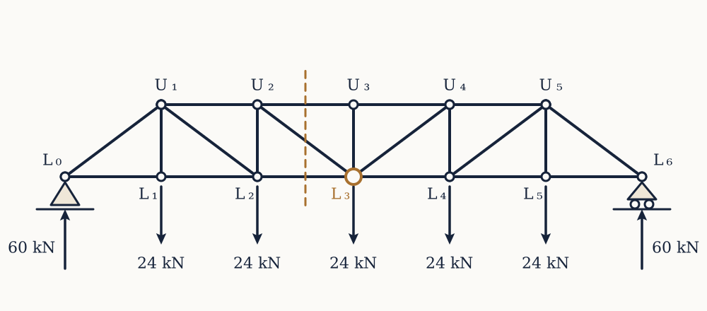
Take a six-panel Pratt through-truss spanning 24 m. The bottom chord runs along y=0 with joints L0 to L6 every 4 m, and the top chord runs at y=3 m with joints U1 to U5 directly above L1 to L5. Verticals join each Li to the Ui above it, end diagonals run from L0 to U1 and from L6 to U5, and the four interior diagonals slope down towards midspan, from U1 to L2, U2 to L3, U5 to L4 and U4 to L3. A deck load puts 24 kN at each of L1 through L5. The total is 120 kN and the truss is symmetric, so each reaction is 60 kN.

Example. Find the force in the top chord member U2U3.

Cut vertically between x=8 m and x=12 m. The cut crosses U2U3, the diagonal U2L3, and the bottom chord L2L3. Keep the left portion, which carries the 60 kN reaction at L0 and the loads at L1 and L2. Two of the cut members, the diagonal and the bottom chord, meet at L3 at (12,0), so take moments there.

Counting anticlockwise as positive, the reaction at L0 is 12 m to the left of L3 and contributes -60×12=-720 kN m. The loads at L1 and L2 are 8 m and 4 m to the left and contribute +24×8=192 and +24×4=96 kN m. The top chord force F acts horizontally at 3 m above the moment point, contributing -3F if it is tensile. Everything else in the cut passes through L3 and drops out. So -720+192+96-3F=0, giving F=-144 kN: the top chord carries 144 kN of compression, which is what a top chord should do.

Now you. Using the same truss and the same cut, find the force in the bottom chord L2L3 by taking moments about U2 at (8,3).

Answer

The diagonal U2L3 and the top chord both pass through U2, so only the bottom chord force survives from the cut. The reaction contributes -60×8=-480 kN m, the load at L1 contributes +24×4=96 kN m, and the load at L2 sits directly below U2 and contributes nothing. A tensile bottom chord force F acting 3 m below the moment point contributes +3F. So -480+96+3F=0 and F=+128 kN, tension.

Solving the whole truss gives a pattern worth reading. The bottom chord runs 80, 80, 128, 128, 80, 80 kN in tension from one end to the other, and the top chord runs 128, 144, 144, 128 kN in compression. Both track the bending moment of an equivalent solid beam, divided by the depth of the truss: the chords are doing the beam's bending and the web members are doing its shear. The end diagonals carry 100 kN of compression and the diagonals nearer midspan only 60 and 20 kN, because shear is largest at the supports and smallest in the middle. The vertical L3U3 at midspan carries exactly zero, since the two diagonals meeting at L3 each contribute 20×0.6=12 kN of upward pull, together taking the whole 24 kN load at that joint.

Counting members and joints

Before analysing anything, count. Each joint gives two equations in a plane, so a truss with j joints supplies 2j equations. The unknowns are the m member forces plus the r reaction components. Then

m+r=2j

is the condition for a statically determinate truss, m+r<2j marks a mechanism with too few bars, and m+r>2j marks an indeterminate truss with more bars than statics can sort out.

Example. Check the six-panel truss above.

Its joints are L0 to L6 and U1 to U5, so j=12. Its members are six bottom chords, four top chords, five verticals, two end diagonals and four interior diagonals, so m=21. A pin and a roller give r=3. Then m+r=24 and 2j=24: determinate, as the section calculations assumed.

Now you. A planar truss has 9 joints, 16 members, a pin at one support and a roller at the other. Classify it.

Answer

m+r=16+3=19 while 2j=18. There is one member more than statics can handle, so the truss is statically indeterminate to the first degree.

As in the previous lesson, the count is necessary and not sufficient. A truss can satisfy m+r=2j and still be a mechanism if the bars are arranged badly, with a redundant bar in one panel paying for a missing one somewhere else. The count catches the common mistakes and the geometry has to be looked at anyway.

What the truss analysis still does not tell you

At the end of all this every member has a number attached: 128 kN of tension in one bottom chord, 100 kN of compression in an end diagonal. Nothing yet says whether any of them survives.

Two gaps remain. The first is that a force is not a verdict: 100 kN would snap a bicycle spoke and would barely register in a bridge chord, so the force has to be compared against the size of the member. That comparison is stress, two lessons away. The second is that tension and compression are not mirror images. A slender bar in compression can fail by bowing sideways at a load far below anything the material would object to, which is the subject of the buckling lesson and the reason truss compression members are stocky while ties can be thin cables.

Before either, there is the more common structural element that a truss was invented to replace over short spans. A beam takes its load anywhere along its length rather than only at joints, so the force it carries varies from point to point, and describing that variation is the next step.

Internal forces

Knowing that a beam pushes back on its supports with 8 kN and 4 kN says nothing about the beam. A truss member was described by one number because its ends were pins, but a beam is loaded along its length, so what it carries at one point is not what it carries at another, and the failure will happen wherever the worst of it is.

Cutting the beam open

Take a beam in equilibrium, imagine a plane slicing through it at a distance x from the left end, and throw the right-hand part away. The left part is not in equilibrium on its own, because the material that was removed used to push on it. Restore that push as a set of forces on the cut face, and the left part is a legitimate free body again.

In a plane the cut face can carry exactly three things, because three is what equilibrium can demand. There is a force along the beam's axis, the axial force N. There is a force across the axis, the shear force V. And there is a couple in the plane, the bending moment M. Everything a beam does internally is those three numbers as functions of position.

By Newton's third law the right-hand part carries the mirror image of the same three actions on its own face, so either side may be used and they must agree. Choosing the side with fewer forces on it is pure convenience, and using the other side as a check is free.

Beams loaded only across their axis have N=0 throughout, which is why a first course concentrates on V and M. Columns, arches and any beam carrying a diagonal cable have all three at once, and the lesson on combined stress puts them back together.

A sign convention that has to be fixed

Shear and moment have no natural sign, so a convention is imposed and then obeyed. The standard one is written in terms of what the internal action does to a short element rather than which direction an arrow points, which is what makes it work from either side of the cut.

The bending moment is positive when it sags: when it makes the beam concave upwards, stretching the bottom fibres and compressing the top ones. Negative bending is hogging, and it happens over the supports of a continuous beam and along any cantilever. The distinction is not cosmetic. Reinforced concrete needs its steel where the tension is, so getting the sign wrong puts the reinforcement in the compression face, which is a real and repeated construction failure.

The shear force is positive when the left-hand part tends to slide upwards relative to the right-hand part. Equivalently, at a cut, the positive shear on a left segment points downwards on the exposed face.

With that fixed, the recipe is mechanical. To find V and M at a section, take the free body to one side, sum the transverse forces on it to get V, and take moments about the cut to get M.

The two standard cases

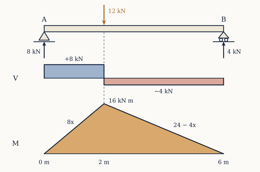
Example. A beam spans 6 m between a pin at A and a roller at B, carrying a point load of 12 kN at 2 m from A. Find the shear and bending moment everywhere.

The reactions were found in an earlier lesson: RA=8 kN and RB=4 kN. For 0<x<2, the left free body carries only RA, so V=+8 kN, constant, and M=8x, rising linearly to 16 kN m at the load. For 2<x<6, the left free body carries RA and the load, so V=8-12=-4 kN, again constant, and M=8x-12(x-2)=24-4x, falling linearly to zero at x=6. Checking from the right at the load point, M=4×4=16 kN m, which agrees.

The shape is worth memorising: under point loads the shear diagram is a set of steps and the moment diagram is a set of straight lines with a peak under the load.

Now you. The same arrangement spans 8 m with a 20 kN load at 3 m from A. Find the shear either side of the load and the maximum bending moment.

Answer

The reactions are RA=12.5 kN and RB=7.5 kN. The shear is +12.5 kN to the left of the load and 12.5-20=-7.5 kN to its right. The maximum moment is under the load, 12.5×3=37.5 kN m, which the right-hand free body confirms as 7.5×5=37.5 kN m.

The other case that appears everywhere is a uniformly distributed load w over the whole span L, which is what a beam's own weight and most floor loads look like. Symmetry gives RA=RB=wL/2. At a section x from the left, the free body carries the reaction and the load wx that sits on it, acting at x/2. So

V(x)=wL2-wxM(x)=wL2x-wx22

The shear falls linearly from +wL/2 to -wL/2 and crosses zero at midspan. The moment is a parabola, zero at both ends, peaking at x=L/2 with

Mmax=wL28

That result is used more than any other in structural engineering, and it is worth carrying the derivation rather than the formula, because the same three lines give the answer for a partial load or an unsymmetrical one where the formula does not apply.

Example. A floor beam spans 8 m and carries 5 kN m⁻¹ over its whole length. Find the end shear and the maximum moment.

V at the supports is wL/2=5×8/2=20 kN. The maximum moment is wL2/8=5×64/8=40 kN m at midspan.

Now you. A beam spans 12 m under 3 kN m⁻¹. Find the same two quantities.

Answer

V=3×12/2=18 kN at each support, and Mmax=3×144/8=54 kN m at midspan.

The two derivatives

Rather than cutting the beam at every position, take an element of length dx carrying a distributed load w downwards. Shear V and moment M act on its left face, and V+dV and M+dM on its right.

Vertical equilibrium of the element gives V-(V+dV)-wdx=0, so

dVdx=-w

Moment equilibrium about the right face gives (M+dM)-M-Vdx+wdxdx/2=0. The last term carries (dx)2 and vanishes in the limit, leaving

dMdx=V

These two turn diagram drawing into calculus. The slope of the shear diagram is minus the intensity of loading, so under no load the shear is constant, under a uniform load it is a straight slope, and at a point load it jumps by the size of the load. The slope of the moment diagram is the shear, so where the shear is constant the moment is linear, where the shear is linear the moment is parabolic, and where the shear passes through zero the moment is stationary.

That last consequence is the working tool: the maximum bending moment occurs where the shear force is zero, or at a point where the shear jumps through zero. Integrating instead of differentiating gives the other half, that the change in moment between two sections equals the area under the shear diagram between them, which is often the fastest way to get a number without writing an equation at all.

A concentrated couple applied to the beam, from a bracket or an offset column, produces a step in the moment diagram and no change at all in the shear, which the two relations predict correctly and intuition usually does not.

Example. A beam spans 10 m between a pin at A and a roller at B, carrying 4 kN m⁻¹ over its whole length plus a 30 kN point load 7 m from A. Where is the maximum moment, and how large is it?

The reactions, found earlier, are RA=29 kN and RB=41 kN. To the left of the point load the shear is V(x)=29-4x, which reaches 29-28=+1 kN just before x=7 and never reaches zero. At the load it drops by 30 to -29 kN. So the shear passes through zero exactly at the point load, and that is where the moment peaks:

M=29×7-4×7×3.5=203-98=105 kN m

Now you. For the same beam, what is the bending moment at midspan, x=5 m?

Answer

The point load is to the right of the cut, so the left free body carries only the reaction and 4×5=20 kN of distributed load acting at 2.5 m. So M=29×5-20×2.5=145-50=95 kN m, less than the peak of 105 kN m under the load.

Cantilevers and overhangs

A cantilever is the case where all the bending is hogging. For a cantilever of length L built in at the left with a point load P at the free end, cutting anywhere gives V=-P and M=-P(L-x), so the moment is largest in magnitude at the support, M=-PL, and zero at the tip. Under a uniform load w the root moment is -wL2/2, four times the midspan moment of a simply supported beam of the same span and load. That factor is why cantilevers are expensive and why a balcony is short.

Overhangs mix the two and produce the one result that surprises people.

Example. A beam has a pin at A at x=0 and a roller at B at x=6 m, and continues as an overhang to a free end at x=8 m, where a 15 kN load hangs. Find the reactions and the moment at B.

Moments about A: RB×6=15×8, so RB=20 kN. Vertical balance gives RA=15-20=-5 kN. The reaction at A is negative, which means the beam is trying to lift off its support there and A must be able to hold it down. Cutting just left of B and using the short right-hand segment, M=-15×2=-30 kN m: hogging over the support, as an overhang always is. Between A and B the moment runs linearly from zero to -30 kN m, so this beam is in hogging over its entire length.

Now you. The same layout has the roller at x=5 m, the free end at x=7 m, and a 24 kN load at the tip. Find RA and the moment at the roller.

Answer

Moments about A: RB×5=24×7, so RB=33.6 kN and RA=24-33.6=-9.6 kN, again an uplift. The moment at the roller is -24×2=-48 kN m.

Uplift is a genuine design case rather than an arithmetic curiosity. A crane counterweight, a cantilevered canopy, and a light roof under wind suction all produce it, and a support detailed to resist only downward force will simply open up.

From diagram to verdict

At this point a beam can be described completely: shear and moment at every section, from the loads and the geometry alone, with no reference to what the beam is made of or how big it is. That independence is exactly why the diagrams are worth drawing first. For a determinate structure the internal forces are settled by statics, so the same diagram serves a timber joist and a steel girder.

It is also why the diagrams cannot decide anything. A moment of 105 kN m is comfortable for a rolled steel section 400 mm deep and hopeless for a 50 mm square timber. To convert an internal action into a verdict, the action has to be spread over the material that carries it, which turns kilonewtons into a quantity that can be compared against a laboratory test on a small sample. That quantity is stress, and it is next.

Stress

A tension of 128 kN in a bridge chord is not yet a statement about safety, because the same 128 kN would part a wire rope and would be nothing at all in a metre of solid steel. Everything so far has produced internal forces; this lesson turns them into the quantity a material property is written in.

Force per unit area

Cut a bar of uniform cross section A carrying an axial force N, and the cut face has to transmit that force. If the force is shared evenly over the face, the intensity of the transmission is

σ=NA

which is the normal stress, normal because it acts perpendicular to the cut face. Its unit is the pascal, one newton per square metre, and the pascal is uselessly small for structures: atmospheric pressure is about 105 Pa and steel yields somewhere near 2.5×10⁸ Pa. So structural work is done in megapascals, and there is an identity that makes the arithmetic almost free:

1 MPa=1 N mm-2

Newtons and millimetres are the units drawings are dimensioned in, so a force in newtons divided by an area in square millimetres comes out directly in megapascals with no conversion at all. This is worth adopting as a habit rather than a trick.

Tension is positive and compression negative, carrying over the convention from the truss lesson. A bar in compression has exactly the same σ=N/A with a negative sign, and everything in this lesson applies to it, with one large caveat about slender members that the buckling lesson deals with.

Example. The midspan bottom chord of the truss analysed two lessons ago carries 128 kN of tension. It is made from a flat steel bar 25 mm by 50 mm. What is the stress, and how does it compare with the yield strength of ordinary structural steel, 275 MPa?

The area is 25×50=1250 mm², so σ=128000/1250=102.4 MPa, about 37 per cent of yield. That is a sensible working figure for a member sized with a margin.

Now you. The same truss has an end diagonal carrying 100 kN of compression. Suppose it is a solid circular rod of 40 mm diameter. What is the stress?

Answer

The area is π×202=1257 mm², so σ=100000/1257=79.6 MPa of compression.

Where the uniform assumption comes from

Dividing by the area assumes the force spreads itself evenly, and near the ends of a bar it does not. Grip a strip in a testing machine and the stress just under the jaws is concentrated wherever the grip bites, varying wildly across the width.

Saint-Venant's principle, stated by Adhémar Barré de Saint-Venant in 1855, is the rescue: two different load distributions with the same resultant force and moment produce essentially the same stress field at distances greater than about the width of the member. A strip 50 mm wide loaded through a pin, a weld, or a clamp all look identical 50 mm in from the end. So the uniform formula is a statement about the middle of a member, and the ends are detailing problems solved by rules of thumb, testing and generous local material.

The principle is not a theorem and it fails where the geometry changes abruptly, which is the subject of the last section here.

Shear stress, and where it is the governing case

If the force on the cut face lies in the plane of the face rather than perpendicular to it, the intensity is a shear stress

τ=VA

again as an average over the face. Shear is what a bolt, a rivet, a weld, a pin and a glue line carry, and connections fail in shear far more often than members fail in tension.

The count of shear planes matters and is easy to get wrong. A bolt joining two overlapping plates has one plane of material sliding over another and is in single shear, so the whole force crosses one bolt cross section. A bolt through a central plate sandwiched between two outer plates is in double shear, with two cross sections sharing the load, so the stress halves for the same force.

Example. A 20 mm diameter bolt in double shear transmits 60 kN. Find the shear stress.

The bolt has area π×102=314.2 mm² per plane, and two planes share the load, so the effective area is 628.3 mm² and τ=60000/628.3=95.5 MPa.

Now you. A 16 mm bolt in single shear transmits 25 kN. Find the shear stress.

Answer

The area is π×82=201.1 mm² on the single plane, so τ=25000/201.1=124.3 MPa.

A third kind appears at the same connection. The bolt presses sideways on the hole it sits in, and the plate can be crushed or torn out even if the bolt itself is fine. The bearing stress is conventionally taken as the force divided by the projected area of contact, the bolt diameter times the plate thickness, which for the 20 mm bolt above through a 12 mm plate gives 60000/(20×12)=250 MPa. That is a large number by design: the convention deliberately understates the true contact area, and the allowable bearing stress is correspondingly set high, often above the material's yield stress, because a little local crushing at a hole is harmless.

A pressure vessel, cut two ways

The neatest use of stress as a bookkeeping quantity is a thin-walled cylinder under internal pressure, because equilibrium alone gives the answer with no material properties involved at all. Take a cylinder of internal radius r and wall thickness t, with t small compared with r, under gauge pressure p.

Cut it lengthways along a diameter and take half the cylinder over a length L as the free body. The pressure acts on the projected area 2rL, pushing the half shell outwards with a force 2prL. The only thing resisting is the wall, cut in two places, each of area tL, carrying a circumferential or hoop stress σθ. Equilibrium gives 2σθtL=2prL, so

σθ=prt

Now cut it across instead, perpendicular to the axis. The pressure acts on the end area πr2 with force pπr2, and the wall resists over a ring of area 2πrt, carrying a longitudinal stress σz. So σz2πrt=pπr2 and

σz=pr2t

The hoop stress is twice the longitudinal stress, which is why a cylindrical vessel that bursts splits along a line parallel to its axis rather than snapping in two, and why a sausage splits lengthways when it is grilled. Both stresses are derived from equilibrium only, so they hold for steel, aluminium, carbon fibre and cardboard alike.

Example. A compressed air receiver has an internal diameter of 1.5 m, a wall thickness of 12 mm, and works at 1.8 MPa gauge. Find both stresses and check the thin-wall assumption.

The radius is 750 mm, so r/t=62.5, comfortably above the usual threshold of 10 for calling a shell thin. Then σθ=1.8×750/12=112.5 MPa and σz=56.25 MPa. Against a yield of 275 MPa the hoop stress carries a factor of about 2.4, which is on the low side for a pressure vessel and is why real codes also demand a corrosion allowance and a weld efficiency factor.

Now you. A pipeline of 600 mm internal diameter and 8 mm wall runs at 2.5 MPa. Find the hoop and longitudinal stresses.

Answer

r=300 mm and r/t=37.5, so the shell is thin. σθ=2.5×300/8=93.75 MPa and σz=46.875 MPa.

Stress concentration

Saint-Venant's principle promises uniformity away from the ends. It says nothing about a hole, a notch, a sharp internal corner or an abrupt change of width, and near those the stress can be several times the average.

The reference case has an exact elastic solution, published by Gustav Kirsch in 1898: a small circular hole in a wide plate under uniform tension σ produces a stress of 3σ at the two edges of the hole on the diameter perpendicular to the load. The stress concentration factor Kt=3 is independent of the size of the hole, which is the counterintuitive part. A pinhole raises the local stress by the same factor as a large one, provided the plate is wide compared with the hole.

Two consequences follow, in opposite directions.

For a ductile material loaded steadily, the concentration matters less than it looks. The material at the hole yields locally, stops taking more stress, and passes the excess to its neighbours, so a mild steel plate with a hole fails at close to the load its net section predicts. This is precisely why bolted steelwork is possible at all.

For a brittle material, or for any material under fluctuating load, it matters enormously. Cast iron and glass have no yielding mechanism to blunt the peak. Fatigue cracks start at concentrations essentially always, which is why the design rule is to round every internal corner generously: the factor for a sharp corner rises without bound as the radius goes to zero. The square windows of the de Havilland Comet, whose corners cracked in 1954 after repeated pressurisation, are the standard illustration, and the aircraft that followed have rounded windows for exactly this reason.

Example. A steel plate 100 mm wide and 10 mm thick carries 40 kN in tension and has a 20 mm hole drilled on its centre line. Estimate the net section stress, and say what the peak stress near the hole would be if Kt were 3.

The net area at the hole is (100-20)×10=800 mm², so the net section stress is 40000/800=50 MPa. A factor of three on that would give 150 MPa. In practice the hole is a fifth of the width rather than tiny, so the true factor is nearer 2.5 and the peak nearer 125 MPa, but either way the plate is comfortable in mild steel and would be a serious concern in cast iron.

Now you. The same plate carries 60 kN instead. What is the net section stress, and does the plate reach a yield of 275 MPa at the hole under a factor of 2.5?

Answer

The net section stress is 60000/800=75 MPa, and 2.5×75=187.5 MPa, still below 275 MPa. Local yielding would not begin, though under a fluctuating load the hole would still be where a crack eventually started.

What one number cannot say

Two limits are worth stating before moving on, and both will be taken up later.

The first is that stress at a point is not one number. A cut through the same point at a different angle exposes a different combination of normal and shear stress, and a bar in pure tension of 100 MPa has a shear stress of 50 MPa on planes at 45 degrees to its axis, which is why a ductile tensile specimen fails on a slanted surface rather than a square one. Describing the state of stress at a point properly needs three numbers in a plane, and the lesson on combined stress does it.

The second is that stress alone cannot solve a structure. Nothing in this lesson has used a material property, which is exactly why the results are so general and also why they cannot supply the missing equations for the indeterminate structures set aside in the first lesson. For that, the material has to be allowed to deform, and how much it deforms under a given stress is a measured property of the substance. That measurement is the next lesson.

Strain and stiffness

Statics ran out of equations in the first lesson, at the beam propped in three places, and stress in the previous lesson did nothing to help because it used no material property at all. The missing conditions are geometric: after the structure deforms, the parts still have to fit together. Writing that down needs a measure of deformation.

Strain

A bar of original length L stretched by an amount δ has normal strain

ε=δL

Strain is a ratio of lengths, so it is dimensionless, and structural strains are small: a steel member working at a sensible stress is strained by roughly one part in a thousand. Because the numbers are inconveniently small they are often quoted in microstrain, one part per million, so a strain of 0.000842 is 842 microstrain. Electrical resistance strain gauges, which are the standard way of measuring it on a real structure, read directly in those units.

Defining strain as the extension divided by the original length is the engineering convention and it is an approximation. For strains beyond a few per cent the length is changing while the stretching happens, and the honest definition integrates dL/L to give true strain ln(L/L0). At structural strains the two agree to better than a tenth of a per cent, so this course uses the engineering definition and the next lesson says where it breaks.

Shear has its own measure. A block whose top face slides sideways relative to its bottom face by Δ over a height h has shear strain γ=Δ/h, which for small distortions is the angle in radians by which a right angle in the material has closed.

The tensile test

Everything about a material's response comes from one experiment. A round bar of known diameter is pulled in a machine that records force and extension, over a marked gauge length so the ends are excluded and Saint-Venant's principle applies. Dividing force by original area and extension by gauge length gives a stress-strain curve, and because both axes are normalised, the curve is a property of the material rather than of the specimen.

The first part of the curve is straight, and its slope is the material's stiffness:

E=σε

called Young's modulus. Robert Hooke published the proportionality in 1676 as an anagram and unscrambled it two years later as ut tensio, sic vis, as the extension so the force; Thomas Young turned it into a material constant in 1807 by dividing out the geometry. Because strain is dimensionless, E has the units of stress and is huge: it is the stress that would double the length of a bar if the material stayed linear that far, which no metal does.

The numbers are worth memorising, because they are the ones that decide how a structure behaves rather than how strong it is. Steel is 210 GPa, and remarkably it is 210 GPa whether the steel is soft mild steel or a high strength alloy: heat treatment changes the strength enormously and the stiffness hardly at all. Aluminium is 70 GPa, one third of steel, which is close to the ratio of their densities too, and a fact the last lesson of this course makes a great deal of. Titanium is 110, glass about 70, ordinary concrete around 30, timber along the grain around 10, nylon about 3, and natural rubber about 0.01, some twenty thousand times less stiff than steel.

Example. A steel rod of 12 mm diameter and 2.5 m length carries 20 kN. Find the stress, the strain and the extension, taking E=210 GPa.

The area is π×122/4=113.1 mm², so σ=20000/113.1=176.8 MPa. Then ε=σ/E=176.8/210000=8.42×10-4, or 842 microstrain. The extension is εL=8.42×10-4×2500=2.11 mm.

Now you. An aluminium rod of 16 mm diameter and 3 m length carries 30 kN, with E=70 GPa. Find the stress and the extension.

Answer

The area is 201.1 mm², so σ=30000/201.1=149.2 MPa. The strain is 149.2/70000=2.13×10-3 and the extension is 2.13×10-3×3000=6.39 mm, three times what a steel rod of the same stress would give.

Combining the definitions in one step gives the formula that does most of the work in this course:

δ=NLAE

Read as a spring, this says the axial stiffness of a bar is k=AE/L newtons per millimetre. A structure is a set of springs, and that is what makes the indeterminate cases solvable.

Poisson's ratio, and strain energy

Stretch a bar and it also gets thinner. The lateral strain is proportional to the axial one, and the constant is Poisson's ratio

ν=-εlateralεaxial

defined with a minus sign so that it comes out positive. For most metals ν is close to 0.3, for concrete about 0.2, for rubber almost exactly 0.5, and for cork nearly zero, which is why a cork can be pushed into a bottle neck and a rubber bung fights back. A value of 0.5 means the volume does not change at all under load, which is why rubber has to be given somewhere to bulge sideways or it behaves as though it were nearly incompressible. Thermodynamic stability limits ν for an ordinary isotropic material to between -1 and 0.5, and engineered foams with re-entrant cells do achieve negative values.

The work done stretching an elastic bar is stored and recoverable. Load rises linearly from zero to N while the extension rises from zero to δ, so the work is the area under that line:

U=12Nδ=N2L2AE

For the steel rod above, U=0.5×20000×0.00211=21.1 J. That looks small until it is compared with what happens when it is released suddenly. Strain energy is why a snapped cable whips, why a bolt tightened into a long grip is a better fastener than a short one, and why toughness matters more than strength for anything that might be hit.

Thermal strain

A material expands when heated, by ε=αΔT, where α is the coefficient of linear thermal expansion. For steel α12×10-6 K⁻¹, for aluminium 23×10-6, for concrete about 10×10-6, which is the happy accident that makes reinforced concrete possible, and for Invar, a nickel-iron alloy discovered by Charles Guillaume in 1896, about 1×10⁻⁶.

If the member is free to move, thermal strain produces no stress at all: it simply gets longer. If it is restrained, the restraint has to squeeze it back to its original length, and the stress required is

σ=EαΔT

which is independent of the length of the member. That is the important and counterintuitive part. A restrained bar 1 metre long and one 100 metres long develop exactly the same thermal stress.

Example. A steel bar is held between two immovable walls and its temperature rises by 40 K. What stress does it develop?

σ=210000×12×10-6×40=100.8 MPa of compression, over a third of the yield strength of mild steel, from a temperature change a sunny afternoon supplies.

Now you. Repeat for an aluminium bar, with E=70 GPa and α=23×10-6 K⁻¹.

Answer

σ=70000×23×10-6×40=64.4 MPa. Aluminium expands twice as much but is three times less stiff, so the stress is lower.

Structures are therefore detailed to let temperature happen. Bridges get sliding bearings and expansion joints, long pipe runs get loops, and rails are either gapped or, in continuous welded track, deliberately stressed at installation so that the working range never reaches buckling. Continuous track that is laid at the wrong temperature buckles sideways in summer, which is a real and regular failure mode.

Compatibility, and the indeterminate structure solved

Now the promise of the first lesson can be kept.

Example. A short reinforced concrete column is a 300 mm square of concrete with four 20 mm steel bars cast into it, carrying 900 kN in compression through a rigid plate at the top. How does the load divide between the two materials?

Equilibrium gives one equation, that the two materials share the load: P=σcAc+σsAs. Two unknown stresses, one equation. The missing equation is compatibility: the plate is rigid and the bars are bonded to the concrete, so both materials shorten by the same amount over the same length, and therefore they have the same strain.

εc=εsσcEc=σsEsσs=EsEcσc

Taking Es=200 GPa and Ec=25 GPa, the modular ratio Es/Ec is 8, so the steel carries eight times the stress of the concrete beside it. The steel area is 4×π×202/4=1257 mm² and the concrete area is 90000-1257=88743 mm². Substituting,

P=σc(Ac+8As)=σc(88743+10053)=98796σc

so σc=900000/98796=9.11 MPa and σs=72.9 MPa. The steel carries 72.9×1257=91.6 kN, which is 10.2 per cent of the load on 1.4 per cent of the area. Stiffness attracts load: in an indeterminate structure, the stiffer path takes the larger share, and that principle is worth more than the arithmetic.

Now you. The same column is reinforced with four 25 mm bars instead. Find the stress in each material and the fraction of the load the steel carries.

Answer

As=4×π×252/4=1963 mm² and Ac=90000-1963=88037 mm². Then Ac+8As=103744, so σc=900000/103744=8.68 MPa and σs=69.4 MPa. The steel force is 69.4×1963=136 kN, or 15.1 per cent of the total.

The same two steps settle the other classic case, a steel bar of uniform section fixed rigidly at both ends with a load P applied at a point dividing it into lengths a and b. Equilibrium gives R1+R2=P and nothing more. Compatibility says the total length is unchanged, so the extension of one portion equals the shortening of the other: R1a/(AE)=R2b/(AE), giving R1a=R2b. Solving, R1=Pb/(a+b) and R2=Pa/(a+b). The shorter portion, being the stiffer spring, takes the larger force, and A and E cancel out entirely because both portions are the same material and section.

The recipe generalises. Write every equilibrium equation available, count the shortfall, and supply exactly that many statements about how the deformed parts must fit. Each one turns into an equation in the unknown forces through δ=NL/AE. This is the whole method for indeterminate structures, and the deflection lesson will use it again on beams.

What the straight line does not cover

Two limits are set by the curve itself.

Hooke's law is the first part of a measured curve, not a law of nature. It holds up to a proportional limit and no further, and past that a structure analysed by these methods is being analysed with the wrong constitutive relation. Where that limit is, and what happens beyond it, is the next lesson.

And even inside the elastic range, E is a single number only for a material that behaves the same in every direction. Timber along the grain is roughly twenty times stiffer than across it. A carbon fibre laminate can be tuned to almost any stiffness in any direction by choosing the ply angles. Concrete is stiff in compression and effectively has no tensile strength at all, which is why it is reinforced. Assuming one isotropic E is correct for steel and for most metals, and it is an approximation that has to be checked for everything else.

Yielding and safety

Hooke's law was introduced in the previous lesson as the first part of a measured curve, and a curve that is only straight at the start has to be followed further before anything can be called safe. This lesson reads the rest of it, and then turns its landmarks into the numbers a design actually uses.

The rest of the tensile curve

Pull a mild steel specimen past the straight portion and five things happen in order, each with a name.

The proportional limit is where the line stops being straight. Just above it lies the elastic limit, the last stress from which the specimen returns to its original length on unloading; in practice the two are close enough that most texts do not distinguish them.

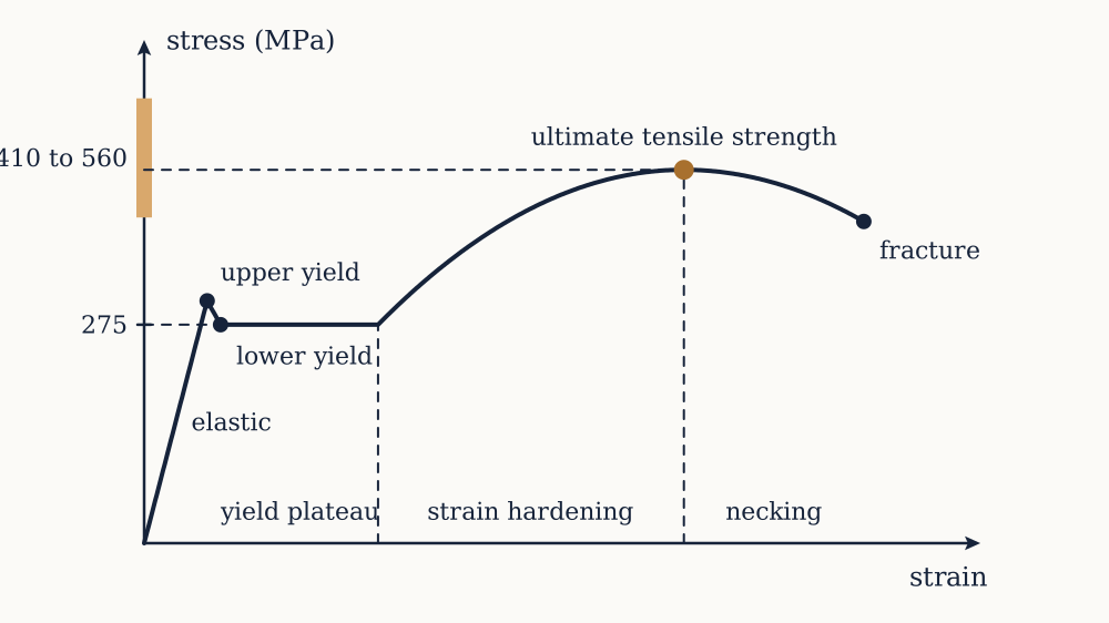
Then mild steel does something unusual and useful: it yields at a well defined stress, and the load actually drops slightly, from an upper to a lower yield point, before the specimen extends at essentially constant load for a strain of one or two per cent. That flat plateau is the yield plateau, and while it is happening bands of sheared material called Lüders bands sweep visibly along the specimen.

After the plateau the material strain hardens and the curve rises again, because the dislocations that carry plastic flow get tangled and impede one another. The peak of the curve is the ultimate tensile strength, the largest engineering stress the specimen sustains.

Past the peak the curve falls, and the fall is a geometric effect rather than a weakening. Deformation localises into a neck where the section is thinning faster than the material is hardening, all further elongation happens in that neck, and the load needed to continue drops even though the material there is getting stronger. Fracture ends it.

For grade S275 structural steel, the yield strength is 275 MPa, the ultimate strength lies between about 410 and 560 MPa, and the elongation at fracture is around 22 per cent. For S355 the yield is 355 MPa and the ultimate between about 470 and 630 MPa. That gap between yield and ultimate is a large part of why steel is a forgiving material: a member that has just started to yield still has half as much again in reserve before anything parts.

Reading a test

Example. A tensile specimen of 12.5 mm diameter is machined with a 50 mm gauge length. It yields at 34 kN, reaches a maximum load of 56 kN, and breaks; afterwards the gauge length measures 66 mm and the diameter at the neck is 8.4 mm. Find the yield strength, the ultimate strength, the percentage elongation and the reduction of area.

The original area is π×12.52/4=122.7 mm². The yield strength is 34000/122.7=277 MPa and the ultimate strength is 56000/122.7=456 MPa, both computed on the original area by convention. The elongation is (66-50)/50=32 per cent. The reduction of area is 1-(8.4/12.5)2=54.8 per cent. Those last two are the standard measures of ductility, and a metal with a few per cent of either is one to be careful with.

Now you. A specimen of 10 mm diameter and 50 mm gauge length yields at 28 kN, peaks at 41 kN, and finishes with a gauge length of 62 mm. Find the yield strength, the ultimate strength and the elongation.

Answer

The area is 78.54 mm². Yield is 28000/78.54=357 MPa, ultimate is 41000/78.54=522 MPa, and the elongation is 12/50=24 per cent. That is roughly an S355 steel.

Engineering stress uses the original area throughout, which is why the curve appears to fall after the peak. True stress, load divided by the actual current area, rises monotonically all the way to fracture. At maximum load the specimen above has extended by about 16 per cent uniformly, so its area has shrunk by about the same factor, and the true stress there is nearer 530 MPa than 456. Design uses engineering stress because the original dimensions are the ones on the drawing, and metal forming uses true stress because it cares what the material is actually doing.

When there is no yield point

Most materials do not oblige with a plateau. Aluminium alloys, copper, high strength steels and most polymers curve away from the straight line gradually, with no single stress at which yielding obviously begins.

The convention is the 0.2 per cent proof stress, sometimes written σ0.2 or Rp0.2: draw a line parallel to the elastic portion, offset by a strain of 0.002, and take the stress where it cuts the curve. That is the stress which leaves 0.2 per cent permanent strain after unloading, which for a 3 metre member is 6 mm of set. Aluminium alloy 6082-T6, the common structural extrusion alloy, has a proof stress near 260 MPa and an ultimate strength near 310 MPa, so its margin between first yield and fracture is far narrower than steel's.

The definition is arbitrary and it is honest about being arbitrary. Nothing physical happens at 0.002; the number is chosen because it is measurable, reproducible and small enough not to matter.

Ductile and brittle

The distinction that governs how a structure fails is whether the material can deform plastically before it parts.

A ductile material yields, redistributes, warns, and absorbs energy. Its tensile and compressive strengths are similar, it is insensitive to stress concentrations under steady load, and it fails on a slanted surface driven by shear. Mild steel, copper, aluminium and most polymers above their glass transition behave this way.

A brittle material fractures with almost no plastic strain, at a stress set by the worst flaw it happens to contain. Its strength is scattered rather than a number, it is far stronger in compression than in tension, it is acutely sensitive to notches, and it gives no warning. Grey cast iron has a tensile strength near 200 MPa and a compressive strength near 800 MPa. Concrete is more extreme still: a common structural grade takes 30 to 40 MPa in compression and about a tenth of that in tension, which is why every concrete design assumes the tension side has already cracked and puts steel there.

The distinction is not a permanent property of a substance. Steel that is ductile at 20 degrees Celsius becomes brittle below a transition temperature, and the transition can sit near ordinary ambient conditions in the wrong composition. Of the 2710 all-welded Liberty ships built during the Second World War, hundreds developed serious hull cracks in cold North Atlantic service and about twenty broke essentially in two. The most quoted case is not a Liberty ship at all but the T2 tanker Schenectady, which split across its deck and down both sides at its outfitting dock in Portland, Oregon, on 16 January 1943, having never been to sea. The investigations that followed established low temperature brittle fracture as a design case and made the Charpy impact test, devised by Georges Charpy in 1901, a routine acceptance requirement for ship plate.

Toughness, and the number a hardness tester gives

The area under the stress-strain curve up to fracture is the energy absorbed per unit volume, and it is the material's toughness. It has units of joules per cubic metre, which reduce to pascals, so toughness is numerically comparable with strength while meaning something entirely different.

Strength and toughness pull against each other. A hardened tool steel may have three times the yield strength of mild steel and a tenth of its elongation, so its toughness is lower despite its strength being higher. For anything that might be struck, dropped, or loaded by an event nobody predicted, toughness is the property that decides whether the structure deforms or shatters, and it is the reason a car body is made of a steel far weaker than the best available.

Hardness is the cheap proxy. A Brinell or Vickers test presses an indenter into the surface and reports load divided by indentation area, and because indentation is essentially a constrained plastic flow it correlates with tensile strength. For steels the rule of thumb is that the ultimate strength in megapascals is roughly 3.4 times the Brinell number, so a hardness of 150 HB suggests about 510 MPa. It is a correlation and not a law, it is calibrated separately for each family of alloys, and it says nothing at all about ductility. Its value is that it is non-destructive and takes a minute, which makes it the standard check on a component that has already been made.

Factors of safety

No structure is designed to reach the stress at which its material fails. The traditional method sets an allowable stress, the yield or ultimate strength divided by a factor of safety, and requires the calculated working stress to stay below it.

The factor is not one number for all time. Victorian practice used four or more on the ultimate strength for cast iron, reflecting scattered material, crude analysis and an unforgiving failure mode. Modern structural steelwork works closer to 1.5 on yield, because the material is delivered to a specification with a guaranteed minimum, the analysis is far better, and the failure mode gives warning. Lifting equipment and pressure vessels sit between. The factor is covering ignorance about the load, ignorance about the material, ignorance about the analysis, and the consequences of being wrong, and it shrinks precisely as those become better known.

Example. A tie carries 128 kN. It is to be made from S275 steel with a factor of safety of 1.67 on yield. What area is needed, and would a 30 mm square bar do?

The allowable stress is 275/1.67=164.7 MPa, so the area required is 128000/164.7=777 mm². A 30 mm square bar has 900 mm², so it is adequate, and its working stress is 128000/900=142 MPa, giving an actual factor on yield of 275/142=1.93.

Now you. A tie carries 200 kN in S355 steel with a factor of safety of 1.5. What area is needed?

Answer

The allowable stress is 355/1.5=236.7 MPa, so the area required is 200000/236.7=845 mm². A 30 mm square bar at 900 mm² would just do it.

Where the margin goes in modern codes

Dividing the strength by one number treats all uncertainty as though it lived in the material, which it does not. The self-weight of a concrete slab is known to a few per cent; the crowd load on the floor above it is not. Applying the same margin to both is either wasteful for one or unsafe for the other.

Modern codes therefore use partial factors, putting a separate factor on each source of uncertainty. In the Eurocodes the usual persistent design combination multiplies permanent actions by 1.35 and the leading variable action by 1.5, then compares the result against a resistance found using material strengths divided by their own factors: 1.0 for steel yielding, 1.15 for reinforcement, 1.5 for concrete in compression. Concrete gets the largest material factor because it is made on site and its strength varies most.

Example. A floor beam of 8 m span carries a permanent load of 20 kN m⁻¹ and a variable load of 15 kN m⁻¹. Find the design bending moment.

The design load is 1.35×20+1.5×15=27+22.5=49.5 kN m⁻¹. The beam is simply supported, so M=wL2/8=49.5×64/8=396 kN m. The section then has to be chosen so that its moment resistance, computed with the material factor already applied, is at least that.

Now you. A beam of 6 m span carries 12 kN m⁻¹ permanent and 18 kN m⁻¹ variable. Find the design moment.

Answer

The design load is 1.35×12+1.5×18=16.2+27=43.2 kN m⁻¹, and M=43.2×36/8=194.4 kN m.

What a factor of safety does not cover

A factor on yield protects against a member being overloaded once, by a static load, at room temperature, in a member with no defects. Four common failures escape it entirely.

Fatigue cracks grow under loads far below yield, provided they are repeated often enough: a welded steel detail may have a fatigue limit under 100 MPa at a few million cycles, well inside any static allowable stress. Fracture propagates from an existing crack when the material's toughness is exceeded, which is governed by crack length and fracture toughness rather than by stress alone. Creep lets a material deform steadily under constant load at high temperature, which is why turbine blades and steam pipes are designed to a stress that limits creep rate rather than to yield. And corrosion, which quietly removes the area every one of these calculations divided by.

Each of those is a subject on its own, and naming them is the point: a stress calculation with a factor of safety on it is a necessary condition and never a sufficient one.

With the material curve in hand, the rest of the course goes back to geometry. Every result so far has assumed the stress is spread evenly over the section, so only the size of a member mattered. The next lesson breaks that assumption for the first time, and once it is broken, shape becomes the main thing an engineer chooses.

Torsion

Every stress calculation so far divided a force by an area, which quietly assumed that every square millimetre of the section worked equally hard. Twist a circular shaft and that stops being true: the material near the axis barely moves at all, and where the metal sits becomes a design variable in its own right.

What twisting does to the geometry

Take a straight shaft of circular section, fix one end, and apply a torque T about the axis at the other. Scribe a line along the surface before loading and it becomes a helix; scribe radial lines on the end face and they stay straight.

Two observations, both confirmed by experiment and both true only for circular sections, carry the entire derivation. Plane cross sections remain plane and do not warp out of their own plane. Radii remain straight, so each cross section rotates as a rigid disc relative to its neighbours. The reason both hold is symmetry: a circular section looks the same after any rotation about the axis, so there is no preferred direction in which warping could occur. A square shaft has corners, has preferred directions, and does warp, which is why the last section of this lesson has to walk the result back.

Given those two facts, consider a point at radius r on a shaft of length L whose far end has rotated through an angle θ radians. A line originally along the axis has been dragged sideways by an arc length rθ over a length L, so the right angle between the axial line and the radius has closed by

γ=rθL

That is a pure shear strain, and it is proportional to r. On the axis it is zero. At the surface it is largest. The material in the middle of a solid shaft is doing almost nothing.

From strain to the torsion formula

Within the elastic range, shear stress is proportional to shear strain through the shear modulus G, so

τ=Gγ=GθLr

The stress rises linearly from zero on the axis to a maximum at the outer surface. G is not an independent property for an isotropic material: it is fixed by E and Poisson's ratio through G=E/[2(1+ν)]. For steel with E=210 GPa and ν=0.3 that gives G=80.8 GPa, and the tabulated value for structural steel is 81 GPa. Aluminium comes out near 26 GPa.

Now impose equilibrium. The shear stress on an annular ring of radius r and thickness dr acts on an area 2πrdr and has a moment arm r about the axis, so it contributes τ2πrdrr to the torque. Substituting for τ and integrating,

T=GθL0R2πr3dr=GθLJ

where the integral has been given a name:

J=r2dA

is the polar second moment of area. Eliminating Gθ/L between the last two results gives the torsion formula, which is normally written as a chain of three equal ratios:

TJ=τr=GθL

The first equality gives stress from torque, the second gives the twist. Notice what J has done: it is the only place the shape of the section enters, and because r appears squared, material far from the axis counts far more than material near it. That is the whole of the shape argument, and it recurs in the bending lesson with J replaced by a different second moment.

The polar second moment

For a solid circle of radius R, the integral above evaluates to πR4/2, or in terms of diameter

J=πd432

For a hollow circular section the integral simply runs from the inner radius outward, so J=π(D4-d4)/32. Nothing else in the derivation changes, because a hollow shaft satisfies the same two geometric observations.

The fourth power is worth pausing on. Doubling the diameter of a solid shaft multiplies its torsional stiffness and its torque capacity at a given stress by sixteen and by eight respectively, while multiplying its weight by four.

Example. A solid steel shaft of 50 mm diameter carries a torque of 1.2 kN m over a length of 1.5 m. Find the maximum shear stress and the angle of twist, taking G=81 GPa.

J=π×504/32=613592 mm⁴. The maximum stress is at the surface, r=25 mm:

τ=TrJ=1.2×106×25613592=48.9 MPa

The twist is θ=TL/GJ=(1.2×106×1500)/(81000×613592)=0.0362 rad, which is 2.08 degrees. A rule of thumb for power transmission shafts is to keep the twist under one degree per metre, and this one is at 1.38 degrees per metre, so it would be sized on stiffness rather than strength.

Now you. A solid steel shaft of 60 mm diameter carries 2 kN m over 2 m. Find the maximum shear stress and the twist in degrees.

Answer

J=π×604/32=1.272×106 mm⁴. Then τ=2×106×30/1.272×106=47.2 MPa, and θ=2×106×2000/(81000×1.272×106)=0.0388 rad, or 2.22 degrees.

Sizing a shaft from the power it carries

Shafts are almost never specified by torque directly. They are specified by the power they transmit and the speed they run at, and the torque follows from mechanics: power is torque times angular velocity, P=Tω, with ω=2πN/60 for a speed of N revolutions per minute.

Combining that with the torsion formula gives the design equation. For a solid shaft, τmax=T(d/2)/(πd4/32)=16T/(πd3), so

d3=16Tπτallow

Example. A solid steel shaft transmits 30 kW at 600 rpm. The allowable shear stress is 50 MPa. What diameter is needed?

ω=2π×600/60=62.83 rad s⁻¹, so T=30000/62.83=477.5 N m, which is 4.775×10⁵ N mm. Then d3=16×4.775×105/(π×50)=48650 mm³, giving d=36.5 mm. A 40 mm shaft would be specified, since that is a stock size and the next one down is not.

Now you. A solid steel shaft transmits 20 kW at 300 rpm with an allowable shear stress of 45 MPa. What diameter is needed?

Answer

ω=31.42 rad s⁻¹ and T=20000/31.42=636.6 N m. Then d3=16×6.366×105/(π×45)=72050 mm³ and d=41.6 mm, so a 45 mm shaft.

Note that halving the speed doubles the torque for the same power, so slow machinery needs fat shafts. This is why a ship's propeller shaft turning at 100 rpm is enormous and a turbine shaft delivering the same power at 3000 rpm is not.

Why shafts are hollow

The linear stress distribution says the core of a solid shaft is nearly idle, and the arithmetic says how nearly.

Example. Compare a solid steel shaft of 60 mm diameter with a hollow one of 60 mm outside and 40 mm bore, on the basis of torque carried per unit of material.

Solid: J=1.272×106 mm⁴ and area 2827 mm². The torque at a given surface stress τ is T=τJ/R=τ×1.272×106/30=42410τ, so torque per unit area is 15.0τ.

Hollow: J=π(604-404)/32=1.021×106 mm⁴ and area 1571 mm². The torque is τ×1.021×10⁶/30=34030τ, so torque per unit area is 21.7τ.

Boring out the middle removes 44 per cent of the material and only 20 per cent of the torsional strength, so the hollow shaft is 44 per cent more efficient per kilogram. This is why drive shafts, bicycle axles and aircraft control tubes are tubes.

Now you. Repeat for a hollow shaft of 60 mm outside and 45 mm bore.

Answer

J=π(604-454)/32=8.698×105 mm⁴ and the area is 1237 mm². The torque is τ×8.698×10⁵/30=28990τ and the torque per unit area is 23.4τ, which is 56 per cent better than the solid shaft.

The limit is not efficiency but local buckling: as the wall gets thinner relative to the diameter, the tube stops failing by shear yielding and starts failing by the wall wrinkling into diagonal folds, which is the same instability the buckling lesson meets in a different guise.

The circular assumption, and what breaks without it

Every result in this lesson rests on cross sections staying plane, and that is a property of the circle. Load a square bar in torsion and the corners of the section pull out of plane in a saddle shape, so the elementary derivation fails at its first step. The maximum shear stress in a rectangular section is not even at the corner furthest from the centre; it is at the midpoint of the longer side, and the corners carry no shear stress at all. Solutions for these cases exist, they come from a different route entirely, Saint-Venant's torsion function, and they are always quoted as tabulated coefficients rather than as a single formula.

The difference that matters most in structures is between closed and open thin-walled sections. A closed tube resists torque by a shear flow that circulates continuously around the wall, and it is very stiff. Slit that tube along its length and the shear flow can no longer circulate, so the section resists only by shearing through its own thickness, and its torsional stiffness collapses by a factor of hundreds for the same amount of material. A rolled steel I-beam is an open section and is therefore hopeless in torsion, which is exactly why a beam carrying an eccentric load has to be checked for twisting separately, and why box girders are used wherever torsion matters, in a curved bridge deck or a crane runway.

Torsion has done its main job for this course, which is to establish that the second moment of the area, not the area, is what a section offers against a moment. Bending applies the same idea in the direction that beams actually work, and the result decides the shape of nearly every structural member ever rolled.

Bending

A bending moment of 40 kN m has been sitting in the diagrams of the third lesson without a verdict attached to it, because dividing a moment by an area gives nothing meaningful. Torsion showed how to handle a case where the stress varies over the section; bending is the same idea applied in the direction beams actually work, and it is the single most used result in structural engineering.

The geometry of a bent beam

Consider a length of beam under pure bending, meaning a constant moment M and no shear. Draw a grid on its side before loading. After loading, the lines that ran across the beam are still straight and still perpendicular to the curved axis; they have simply rotated relative to one another. The lines that ran along the beam have become arcs, longer near the convex face and shorter near the concave one.

The observation that the cross sections stay plane is the Bernoulli assumption, and like the corresponding assumption in torsion it is an experimental fact for slender members rather than a theorem. Jacob Bernoulli reasoned about the bent elastica in 1694, and Leonhard Euler put the theory in its modern form in 1744, though the correct location of the neutral axis waited until Navier's lectures in 1826.

Somewhere between the stretched face and the compressed one is a surface whose length does not change, the neutral surface, and its trace on any cross section is the neutral axis. Measure y from that axis, and let R be the radius of curvature of the neutral surface.

A fibre at distance y originally had length Rdφ along with the neutral surface and now has length (R+y)dφ. So its strain is

ε=(R+y)dφ-RdφRdφ=yR

Strain varies linearly with distance from the neutral axis, and while the material is elastic so does stress:

σ=Eε=ERy

That is the entire physical content. Everything else is bookkeeping over the section.

Where the neutral axis sits

Nothing so far said where the neutral axis is, and equilibrium settles it. Under pure bending there is no net axial force on the section, so

σdA=ERydA=0

Since E/R is not zero, ydA=0, and that integral vanishing is precisely the definition of the centroid. So the neutral axis passes through the centroid of the cross section, whatever its shape.

For a rectangle or an I-section symmetric about its horizontal axis, that is at mid-depth and the maximum tensile and compressive stresses are equal. For a T-section, a channel, or a rail, the centroid is nearer one face, and the two extreme stresses differ, sometimes by a factor of two or more. That asymmetry is exploited on purpose in cast iron beams and in reinforced concrete, where the material is much better in compression than in tension and the section is arranged so the small stress lands on the weak face.

The flexure formula

Now take moments about the neutral axis. Each element of area contributes a force σdA at a lever arm y, so

M=σydA=ERy2dA=EIR

where

I=y2dA

is the second moment of area about the neutral axis, with units of length to the fourth power. Eliminating E/R between this and the stress relation gives the flexure formula, written as the same chain of ratios as in torsion:

MI=σy=ER

Three readings, all used constantly. The first gives the stress at any depth from the moment. The third says the curvature is 1/R=M/EI, so EI is the flexural rigidity and it is what the deflection lesson integrates. And the quantity I is again a purely geometric property of the section, with y squared, so material far from the neutral axis matters far more than material near it.

The largest stress occurs at the extreme fibre, at y=ymax, so it is convenient to combine the two geometric quantities into the section modulus

Z=Iymaxσmax=MZ

Z has units of length cubed and is the single number a beam catalogue quotes for strength in bending. Steel section tables give it in cubic centimetres, which is why a design calculation shuttles between millimetres and centimetres more than it should.

Second moments, and the parallel axis theorem

For a rectangle of width b and depth d bent about its horizontal centroidal axis, the integral runs from -d/2 to d/2 over strips of area bdy:

I=-d/2d/2by2dy=bd312

For a solid circle of diameter d it comes out as πd4/64, exactly half the polar value from the torsion lesson, which is what you would expect since J=Ix+Iy and the two are equal by symmetry.

Real sections are built up from rectangles that are not all centred on the same axis, and the parallel axis theorem handles that. For an area A whose own centroidal second moment is Ic, about an axis a distance h away,

I=Ic+Ah2

The proof is one line: expand (y+h)2dA into y2dA+2hydA+h2dA, and the middle term vanishes because y is measured from the centroid.

Example. A T-section has a flange 150 mm wide and 20 mm thick sitting on top of a web 20 mm wide and 130 mm tall, so the overall depth is 150 mm. Find the position of the neutral axis and the two section moduli.

Flange: area 3000 mm², centroid 140 mm above the bottom. Web: area 2600 mm², centroid 65 mm above the bottom. The centroid of the whole is

y=3000×140+2600×655600=5890005600=105.2 mm

Applying the parallel axis theorem to each piece about that level:

I=[150×20312+3000(34.8)2]+[20×130312+2600(40.2)2]=1.160×107 mm4

The extreme fibres are 105.2 mm below and 44.8 mm above the neutral axis, so Zbottom=1.160×10⁷/105.2=110300 mm³ and Ztop=1.160×10⁷/44.8=258700 mm³. The smaller one governs, so this section is limited by the stress in its bottom fibre, which under sagging is tension.

Now you. A T-section has a flange 200 mm by 25 mm on a web 25 mm by 175 mm, overall depth 200 mm. Find the neutral axis position and I.

Answer

The flange has area 5000 mm² at 187.5 mm and the web 4375 mm² at 87.5 mm, so y=(937500+382813)/9375=140.8 mm from the bottom. Then I=[200×253/12+5000(46.7)2]+[25×1753/12+4375(53.3)2]=3.476×107 mm⁴, and the governing section modulus is the bottom one, 3.476×10⁷/140.8=246800 mm³.

Why beams are deep

The cube on the depth in bd3/12 is the most consequential exponent in structural engineering, and it is worth meeting it on a real member.

Example. A timber floor joist 50 mm wide and 200 mm deep spans 4 m and carries 3 kN m⁻¹. Find the maximum bending stress, and compare it with the same joist laid flat.

The maximum moment is wL2/8=3×16/8=6 kN m. On edge, I=50×2003/12=3.333×107 mm⁴ and Z=I/100=333300 mm³, so σ=6×10⁶/333300=18.0 MPa. Grade C24 softwood has a characteristic bending strength of 24 MPa, so this joist is working hard but plausibly.

Now you. The same joist is laid flat, 200 mm wide and 50 mm deep. Find the stress.

Answer

I=200×503/12=2.083×106 mm⁴ and Z=I/25=83330 mm³, so σ=6×10⁶/83330=72.0 MPa, four times as much, from exactly the same piece of wood. It would break.

The factor of four is not an accident of these numbers. Swapping b and d in a rectangle changes Z=bd2/6 by the ratio (d/b), so a joist four times deeper than it is wide is four times stronger in bending on edge. In stiffness the penalty is worse still, since I changes by (d/b)2, a factor of sixteen here.

The I-beam

If material far from the neutral axis earns its keep and material near it does not, the logical section puts almost everything at the extremes and leaves just enough in the middle to hold the two halves together. That is the I-beam, and it is why steel is rolled into that shape rather than any other.

Example. An I-section has two flanges 200 mm wide and 15 mm thick with a web 8 mm thick, giving an overall depth of 300 mm. Compare it with a solid square of the same cross-sectional area.

Compute I as a full rectangle minus the two voids beside the web: I=(200×3003-192×2703)/12=1.351×108 mm⁴. The area is 2×200×15+270×8=8160 mm², and Z=I/150=900500 mm³.

A solid square of 8160 mm² has a side of 90.3 mm, so I=90.34/12=5.55×106 mm⁴ and Z=5.55×10⁶/45.2=122900 mm³.

The I-section has 7.3 times the bending strength and 24 times the bending stiffness of the same weight of steel arranged as a square. That is the entire argument for the shape, and it is why rolled sections are quoted by depth and mass per metre rather than by area.

Now you. A welded plate girder has flanges 300 mm wide and 20 mm thick with a web 10 mm thick, giving an overall depth of 800 mm. Find I and Z.

Answer

I=(300×8003-290×7603)/12=2.191×109 mm⁴, and Z=I/400=5.479×106 mm³, six times the section modulus of the 300 mm deep section above for only 2.4 times the area.

The limit on the argument is that flanges cannot be made indefinitely wide and thin, nor webs indefinitely slender, because both then buckle locally under the compression they are carrying. Steel design codes classify sections into four classes on exactly that basis, and a section too slender to reach its yield stress before a flange buckles is designed to a reduced capacity.

What the flexure formula assumes

Five assumptions were made, and each has a range.

The material is linear and elastic, so the formula stops at first yield. Steel design routinely goes beyond, using a plastic section modulus that assumes the whole section has yielded, which for a rectangle gives bd2/4 against the elastic bd2/6, a reserve of fifty per cent.

The beam is initially straight and bent about a principal axis of the section. Bend a channel about a random axis and it twists as well as bends, which is why unsymmetric bending is a separate topic.

The section is constant and the beam is slender: the plane sections assumption gets steadily worse as the span-to-depth ratio falls below about ten, and a deep beam or a corbel is designed by other methods entirely.

The bending is pure. Real beams carry shear at the same time as moment, and shear makes the sections warp slightly out of plane, contradicting the derivation. The effect on bending stress is small for slender beams, which is why the formula survives, but the shear itself is not small and it has its own stress distribution to work out. That is next.

Finally, the beam is free to bend in the plane of the load. A tall narrow beam loaded on its strong axis can fail instead by buckling sideways and twisting, at a moment well below the one this lesson would predict. That is lateral torsional buckling, and it belongs with the buckling lesson.

Shear in beams

The previous lesson derived bending stress under the fiction of pure bending, a constant moment with no shear. Almost no real beam is in that state: the moment varies along the span, and the third lesson showed that its rate of change is exactly the shear force. Working out what that shear does inside the section explains why beams have webs and why a stack of planks is not a beam.

Why there has to be horizontal shear

Stack three loose planks and load them across a span. They bend together, and their ends slide relative to one another, leaving three visible steps. Glue the same three planks into one block and the ends stay flush, so the glue must be carrying the force that the sliding was previously relieving. The glued beam is also far stronger, because its depth is three times greater and I goes as depth cubed.

The same argument works on a single beam. Take a slice of beam of length dx and consider only the material above some horizontal level. On the left face the bending stresses come from a moment M; on the right face they come from M+dM. The stresses on the right are larger, so the horizontal forces on the two faces do not balance, and the imbalance has to be carried by a shear force on the horizontal plane at the bottom of the piece being considered. There is no other surface available.

So bending that varies along the span implies horizontal shear inside the section, always. It is not an extra load; it is a consequence of the bending already there.

Complementary shear

Shear stresses cannot exist alone on one plane. Take a small square element with a shear stress τ on its top and bottom faces. Those two form a couple, and nothing balances it unless equal shear stresses act on the vertical faces as well, forming an opposing couple. Taking moments about the centre of a square element of side a and thickness t shows the two magnitudes are equal.

τhorizontal=τvertical

This is the complementary shear result, and it is why the shear force V that the diagrams give, which is plainly a vertical action, can be used to find a horizontal stress. It also explains why a free surface always has zero shear stress parallel to it, since there is no material outside to supply the complement, and that boundary condition is what pins the distribution at the top and bottom of a beam.

The shear stress formula

Return to the slice of length dx and take everything above a level y1. The bending stress at a height y is My/I, so the total horizontal force on the left face of the piece is (My/I)dA over the part of the section above y1, and on the right face the same with M+dM. The difference is

dMIydA=dMIQ

where Q=ydA is the first moment of area of the part of the section above the level considered, taken about the neutral axis. It is easiest computed as area times the distance from the neutral axis to that area's own centroid.

That difference is resisted by a shear stress τ acting on the horizontal cut, whose area is tdx with t the width of the section at that level. Balancing, τtdx=QdM/I, and using dM/dx=V,

τ=VQIt

Read the formula through Q. At the very top of the section there is no area above the cut, so Q=0 and the shear stress is zero, as the free surface demands. Moving down, Q grows, and it is largest at the neutral axis, where the whole of one half of the section lies above the cut. So shear stress is largest at the neutral axis and zero at the extreme fibres, which is precisely the opposite of the bending stress distribution. A beam's most highly bent material carries no shear, and its most highly sheared material carries no bending stress.

The rectangular section

For a rectangle of width b and depth d, the area above a level y is b(d/2-y) and its centroid sits at (d/2+y)/2, so

Q=b2(d24-y2)

Substituting with I=bd3/12 and t=b gives a parabola in y, zero at both faces and maximum at y=0:

τmax=3V2A

Fifty per cent more than the average V/A, and worth remembering because the average is what a first guess uses.

Example. A timber beam 100 mm wide and 250 mm deep carries a shear force of 30 kN. Find the maximum shear stress.

The area is 25000 mm², so the average is 30000/25000=1.2 MPa and the maximum is 1.5×1.2=1.8 MPa at the neutral axis. That sounds trivially small next to the bending stresses of the previous lesson, and it is not, because timber's shear strength parallel to the grain is only a few megapascals: an order of magnitude below its bending strength, since the failure is a split running between the fibres rather than across them.

Now you. A timber beam 75 mm wide and 200 mm deep carries 20 kN of shear. Find the maximum shear stress.

Answer

A=15000 mm², so the average is 1.33 MPa and the maximum is 1.5×1.333=2.0 MPa.

Timber beams are therefore checked for shear as a matter of routine, and they are notched at their ends only with great care, because a notch on the tension face puts a re-entrant corner exactly where the shear is trying to split the beam.

The I-beam, and where the shear actually goes

For a section whose width changes, the t in the denominator produces a discontinuity, and in an I-beam it is dramatic.

Example. Take the I-section of the previous lesson: flanges 200 mm by 15 mm, web 8 mm thick, overall depth 300 mm, with I=1.351×108 mm⁴. It carries a shear force of 250 kN. Find the shear stress at the neutral axis, and just above and just below the flange-to-web junction.

At the neutral axis, Q is the flange plus the upper half of the web: 200×15×142.5+8×135×67.5=427500+72900=500400 mm³. With t=8 mm,

τ=250000×5004001.351×108×8=115.8 MPa

At the junction, Q is the flange alone, 427500 mm³. Taken in the web, where t=8 mm, τ=98.9 MPa. Taken in the flange one millimetre higher, where t=200 mm, the same Q gives τ=4.0 MPa. The stress drops by a factor of twenty-five across a boundary where nothing physical changes except the width available to carry it.

Now you. The same section carries 150 kN of shear. Find the stress at the neutral axis, and compare it with the crude estimate V divided by the web area.

Answer

τ=150000×500400/(1.351×108×8)=69.5 MPa. The crude estimate is 150000/(300×8)=62.5 MPa, which is 10 per cent low, and that is the usual size of the error.

Two conclusions follow, and both are standard practice. First, the web carries essentially all the shear in an I-beam, the flanges almost none, so the rough check τV/(dtw) using the full depth times the web thickness is close enough for design and errs on the unsafe side by about ten per cent, which codes correct for. Second, the flanges carry the bending and the web carries the shear, so the two checks are almost independent and a section can be chosen for moment and then verified for shear.

The web has its own failure modes that the stress formula does not see. A slender web buckles diagonally under shear long before it yields, which is why plate girders carry vertical stiffeners. And a web can crush locally where a concentrated load or a support reaction is delivered into it, which is called web bearing or crippling and is checked separately at every point load.

Shear flow, and the spacing of connectors

For a built-up member the useful quantity is not the stress but the force per unit length along the joint, the shear flow

q=VQI

in newtons per millimetre, where Q now refers to the area of the piece being attached. Multiply by the spacing of the fasteners and you get the force each one has to carry, which is how nail, screw, bolt and weld spacing is decided in every built-up beam.

Example. A timber T-beam is made by nailing a flange 200 mm wide and 50 mm thick on top of a web 50 mm wide and 200 mm deep, giving an overall depth of 250 mm. The shear force is 4 kN, and the nails have a capacity of 1200 N each, used in pairs across the joint. What spacing is needed?

Both pieces have area 10000 mm², with centroids 225 mm and 100 mm above the bottom, so the neutral axis is at 162.5 mm. The parallel axis theorem gives I=1.135×108 mm⁴. For the flange, Q=10000×(225-162.5)=625000 mm³. So

q=4000×6250001.135×108=22.0 N mm-1

A pair of nails carries 2400 N, so the spacing is 2400/22.0=109 mm. Round down to 100 mm and specify that.

Now you. The same beam carries 6 kN of shear. What spacing is now needed?

Answer

q=6000×625000/1.135×108=33.0 N mm⁻¹, so the spacing is 2400/33.0=73 mm. In practice, nails would be closer near the supports where V is largest and further apart near midspan, since q follows the shear diagram.

When shear governs, and what the formula misses

Compare the two demands on a simply supported beam of span L under a uniform load. The moment is wL2/8 and the shear is wL/2, so the ratio of bending demand to shear demand grows with the span. Long beams are governed by bending, short deep ones by shear, and the crossover for a rectangular timber section is somewhere around a span of ten to fifteen times the depth. A lintel over a doorway, a bracket, and a beam with a heavy load close to a support are all cases where shear decides, and where a designer who checked only bending would be wrong.

The formula has real limits. It assumes the shear stress is uniform across the width t at any level, which is a good approximation for a narrow web and a poor one for a wide flange, where the true distribution varies across the width and the flange also carries shear flowing horizontally rather than vertically. That horizontal flange shear is what makes a channel section twist unless it is loaded through a particular point, the shear centre, offset outside the web.

It also assumes elastic behaviour and slender geometry, so it does not describe a deep beam, and it says nothing about the buckling failures that usually get a thin web first.

With bending stress and shear stress both in hand, a beam can be checked for strength. It can still be entirely unusable, because a floor that bounces or a lintel that sags visibly has failed in the eyes of everyone who uses it while remaining comfortably below every stress limit. Deflection is next.

Deflection

A beam that satisfies every stress check can still be unusable. A floor that visibly sags, a lintel that lets a door bind, a gantry that whips under a moving load: none of those is a failure of strength, and all of them are failures. This lesson computes how much a beam moves, which turns out to use a result already derived and to supply, as a bonus, the missing equations for indeterminate beams.

The equation of the deflected shape

The flexure formula of two lessons ago ended in a relation that has not yet been used:

1R=MEI

The curvature of the beam at any point is its bending moment divided by its flexural rigidity. From calculus, the curvature of a curve v(x) is

1R=d2v/dx2[1+(dv/dx)2]3/2

and for a structural beam the slope dv/dx is a small number: a beam deflecting by span over 300 has a maximum slope of order 0.01, whose square is 10-4. Dropping it costs a hundredth of a per cent and leaves the Euler-Bernoulli beam equation

EId2vdx2=M(x)

with v measured upwards. Integrating once gives the slope and a constant; integrating again gives the deflection and a second constant. The two constants come from boundary conditions: zero deflection at a pin or a roller, zero deflection and zero slope at a built-in end, and continuity of both across any interior point.

Everything about deflection follows from that. There are quicker routes for complicated cases, the moment-area method, Macaulay's step functions, virtual work, but they are all bookkeeping devices over the same integration.

The cantilever, done in full

Take a cantilever of length L, built in at x=0, carrying a point load P downwards at the free end.

Cutting at x and using the right-hand free body, the moment is M(x)=-P(L-x), hogging throughout. So

EIv′′=-P(L-x)

Integrating, EIv=-PLx+Px2/2+C1. The built-in end has zero slope, so v(0)=0 gives C1=0. Integrating again, EIv=-PLx2/2+Px3/6+C2, and v(0)=0 gives C2=0. At the tip,

v(L)=1EI(-PL32+PL36)=-PL33EI

The minus sign says downwards, and the magnitude PL3/3EI is the standard result. The cube on the length is the thing to carry away: doubling a cantilever's projection multiplies its tip deflection by eight at the same load, and by sixteen if the load is a uniform one that also doubles in total.

Example. A steel cantilever projects 2.5 m and carries 15 kN at its tip. Its second moment of area is 8×107 mm⁴ and E=210 GPa. Find the tip deflection.

Working in newtons and millimetres, v=15000×25003/(3×210000×8×107)=4.65 mm. Against a projection of 2500 mm that is span over 538, which for a cantilever is usually assessed against the projection doubled, and is comfortable.

Now you. A steel cantilever projects 3 m with 10 kN at the tip and I=1.2×108 mm⁴. Find the tip deflection.

Answer

v=10000×30003/(3×210000×1.2×108)=3.57 mm.

Repeating the integration with a uniform load w over the whole cantilever, where M(x)=-w(L-x)2/2, gives a tip deflection of wL4/8EI.

The simply supported beam

For a simply supported span L under a uniform load w, the moment was found in the third lesson as M(x)=wLx/2-wx2/2. So

EIv′′=wLx2-wx22

Integrate: EIv=wLx2/4-wx3/6+C1. Integrate again: EIv=wLx3/12-wx4/24+C1x+C2. Now v(0)=0 gives C2=0, and v(L)=0 gives wL4/12-wL4/24+C1L=0, so C1=-wL3/24. By symmetry the maximum is at midspan, and substituting x=L/2,

vmax=-5wL4384EI

The fourth power of the span is why doubling a span is so much more expensive than it looks: the same beam under the same load per metre deflects sixteen times as far, and it also carries four times the moment.

Example. A steel beam spans 8 m and carries 12 kN m⁻¹, with I=2.5×108 mm⁴ and E=210 GPa. Find the maximum deflection and compare it with the usual limits.

Convert: w=12 N mm⁻¹ and L=8000 mm. Then

v=5×12×80004384×210000×2.5×108=12.2 mm

The common limits are span over 360 for the deflection caused by imposed load on a floor and span over 250 for the total, which here are 22.2 mm and 32 mm. The beam passes.

Now you. A steel beam spans 10 m under 8 kN m⁻¹ with I=3.5×108 mm⁴. Find the maximum deflection and check it against span over 360.

Answer

v=5×8×100004/(384×210000×3.5×108)=14.2 mm, against a limit of 10000/360=27.8 mm. It passes comfortably.

Two more standard cases complete the set most design work needs. A simply supported beam with a central point load P deflects PL3/48EI, and one with a moment M0 applied at one end deflects a maximum of M0L2/(93EI).

Superposition, and sizing for stiffness

Because the beam equation is linear in v, the deflection under several loads is the sum of the deflections under each separately. That turns a table of four or five standard cases into a method for almost any real loading: split the load into recognisable pieces, look each one up, and add.

Superposition also inverts cleanly, which is how beams get sized for stiffness rather than strength. Rearranging the uniform load result for I,

Irequired=5wL4384Evlimit

Example. A floor beam spans 6 m under 10 kN m⁻¹ and must not deflect more than span over 360. What second moment of area does it need?

The limit is 6000/360=16.7 mm, so I=5×10×60004/(384×210000×16.7)=4.82×107 mm⁴. Compare that with the strength requirement: the moment is 10×36/8=45 kN m, so at 275 MPa the section modulus needed is 164000 mm³, which for a beam 300 mm deep corresponds to I of about 2.5×107 mm⁴. Stiffness asks for roughly twice as much section as strength does, which is typical for steel floors and is why deflection, not stress, usually chooses the beam.

Now you. A floor beam spans 5 m under 12 kN m⁻¹ with the same limit of span over 360. What second moment of area does it need?

Answer

The limit is 5000/360=13.9 mm, so I=5×12×50004/(384×210000×13.9)=3.35×107 mm⁴.

The reason is a scaling one. Stress limits are set by material strength, which for steel has risen over the last century; deflection limits are set by E, which has not moved at all. Higher grade steel buys strength and buys nothing whatever in stiffness, so as grades improve, more and more members end up sized by deflection.

A shortcut used constantly on site is the span-to-depth ratio. Because I scales as d3 and Z as d2, the deflection under a given load per metre depends mostly on L/d, and a rule such as "a simply supported steel floor beam at about L/20, a timber joist at about L/16, a reinforced concrete slab at about L/26" gets a first size in one step. It is a way to start, not a way to finish.

The propped cantilever

The first lesson set aside structures with more reactions than equations. Deflection supplies the missing ones.

Example. A beam of span L is built in at A and simply propped at B, carrying a uniform load w. Find the reaction at the prop.

There are four unknowns, two forces and a fixing moment at A, and one force at B, against three equations. Take the prop force R as the redundant, remove the prop, and treat the result as a plain cantilever carrying two things: the uniform load, and an upward point load R at the tip.

Under w alone the tip would drop wL4/8EI. Under R alone it would rise RL3/3EI. The prop is rigid, so the true deflection there is zero, and that is the compatibility condition:

wL48EI=RL33EIR=3wL8

Everything else follows from statics. The built-in end takes wL-3wL/8=5wL/8, and its fixing moment is wL2/2-(3wL/8)L=wL2/8, hogging. The largest sagging moment works out at 9wL2/128, about 56 per cent of the simply supported value, and the maximum deflection is wL4/185EI, about two fifths of the simply supported one. Adding a prop buys a great deal.

Note what disappeared: E and I cancelled, so the answer holds for any material and any section, provided the beam is uniform. That cancellation is a general feature of indeterminate structures with one material throughout, and it is why the classical results can be tabulated at all.

Now you. A propped cantilever of 6 m span carries 20 kN m⁻¹. Find the prop reaction, the reaction at the built-in end, and the fixing moment.

Answer

R=3×20×6/8=45 kN at the prop, so the built-in end takes 120-45=75 kN, and the fixing moment is wL2/8=20×36/8=90 kN m, hogging.

What the integration leaves out

Three limits are worth stating.

The equation used only bending. Beams also deflect because of shear distortion, which the derivation ignored entirely. For a slender beam that is right to within a per cent or two, but for a span less than about ten times the depth the shear contribution becomes significant, and for a sandwich panel with a soft core it can dominate.

The small slope approximation was made explicitly, so the results describe deflections that are small compared with the span. A fishing rod, a leaf spring or a diving board bends far enough that the exact curvature has to be kept, and the resulting elastica problem has no elementary solution.

And EI was assumed constant and known. For steel that is fine. For reinforced concrete it is not, because the section cracks in tension under service load and its effective I drops to somewhere between a third and a half of the uncracked value, and it goes on deflecting for years afterwards under creep, typically doubling the initial figure. Concrete deflection calculations therefore carry uncertainties of tens of per cent, which is why concrete codes prefer to control deflection with span-to-depth rules rather than by calculating it.

Every result so far, in bending and in deflection alike, has assumed the beam fails when the material gives way. For a member in compression that assumption is simply false, and the next lesson shows how badly.

Buckling

Every check so far has compared a stress against a material limit, and for members in tension that is the whole story. Push on a metre rule instead of pulling it and something else happens entirely: it bows out sideways and loses all resistance, long before anything in it has come close to yielding. That failure has nothing to do with strength, and it is the reason compression members look nothing like tension members.

Why compression is not tension with a sign flipped

A tie in tension is self-straightening. If it starts slightly bent, the pull tends to pull it straight, and any small sideways disturbance is corrected by the load itself. A strut in compression is the opposite: a small bow gives the axial load an eccentricity, the eccentricity produces a bending moment, the bending moment increases the bow. Whether that loop settles or runs away depends on how stiff the member is in bending against how hard it is being pushed.

So a compression member has two entirely separate failure loads. It can be squashed, when the stress reaches the yield strength, at a load σyA. Or it can buckle, at a load that turns out to depend on E, on I, and on the length, and not at all on the material's strength. The lower of the two governs, and for anything slender the second is far lower.

This is the failure mode that has to be found by calculation rather than by inspection, because a buckled member is not overstressed anywhere at the moment it goes.

Euler's derivation

Leonhard Euler solved the problem in 1744, and the derivation uses the beam equation of the previous lesson with one change of sign.

Take a strut of length L, pinned at both ends so that neither end can move sideways and neither resists rotation, carrying an axial compressive load P. Suppose it has adopted a bowed shape v(x). At a section x, the free body between the end and the cut has the load P acting at the end, offset from the cut by the deflection v, so the internal bending moment is M=-Pv, the sign because the moment acts to increase the bow. Substituting into EIv′′=M,

EId2vdx2+Pv=0

This is the equation of simple harmonic motion with x in the role of time. Writing k2=P/EI, the general solution is

v=Asinkx+Bcoskx

The boundary conditions are v=0 at both ends. The first gives B=0. The second gives AsinkL=0, and here is the whole subtlety: either A=0, meaning the strut stays perfectly straight, which is a valid solution at every load, or sinkL=0, which requires

kL=nπP=n2π2EIL2

At those particular loads, and only at those, a bowed shape is possible alongside the straight one. The smallest, with n=1, is the Euler critical load

Pcr=π2EIL2

and the shape that goes with it is a single half sine wave.

The equation never determines A. That is not a failure of the algebra; it is the physics. At the critical load the strut is indifferent to being bowed by any amount, which is exactly what neutral equilibrium means, and it is why buckling is an eigenvalue problem rather than a stress problem. A small increase past Pcr and the deflection is limited only by the large-deflection terms that were dropped, which is to say the member folds.

Reading the result

Three things are in the formula and one large thing is not.

The load falls as the square of the length, so doubling a strut's length quarters what it can carry. Nothing else in this course punishes length so heavily.

It rises with EI, so it is stiffness that resists buckling. In particular, I must be taken about the axis the strut will actually bend about, which is the one with the smallest second moment. A strut buckles the easy way, and a rectangular strut 50 mm by 100 mm will always go about the weak axis unless something restrains it there.

And the strength of the material is absent entirely. A strut in S275 steel and a geometrically identical one in S355 buckle at the same load, because E is the same for both. Paying for higher grade steel in a slender compression member buys nothing at all, which is one of the more expensive lessons in the subject to learn on site.

Example. A solid steel rod of 50 mm diameter is used as a pin-ended strut 2.5 m long. Find its Euler load, and compare it with the load that would squash it, taking σy=275 MPa and E=210 GPa.

I=π×504/64=3.068×105 mm⁴, and A=1963 mm². Then

Pcr=π2×210000×3.068×10525002=101.7 kN

The squash load is 275×1963=540 kN. Buckling governs at under a fifth of it, so four fifths of this rod's strength is unusable at this length.

Now you. The same rod is used over 1.5 m instead. Find the Euler load.

Answer

Pcr=π2×210000×3.068×105/15002=282.6 kN. Shortening the strut by 40 per cent has nearly tripled it, and it is still only half the squash load.

Effective length

The derivation used pinned ends because they give the simplest boundary conditions. Other end conditions change the shape of the buckled curve, and the change can be absorbed entirely into an effective length Le, the distance between the points of inflection in the buckled shape, so that

Pcr=π2EILe2

Four cases cover almost everything. Pinned at both ends gives Le=L, by definition. Fixed at both ends gives Le=0.5L, so four times the load. Fixed at one end and pinned at the other gives Le=0.7L, roughly twice the load. Fixed at one end and entirely free at the other, a flagpole, gives Le=2L, so a quarter of the load.

The spread between the best and worst of those is a factor of sixteen, which makes end restraint the cheapest thing an engineer can buy in a compression member.

Example. Take the same 2.5 m, 50 mm rod. What is its critical load if both ends are fully fixed, and what if it is a free-standing post fixed only at its base?

Fixed at both ends, Le=1250 mm and Pcr=407 kN, four times the pinned value and now approaching the squash load. As a free-standing post, Le=5000 mm and Pcr=25.4 kN, one quarter of the pinned value.

Now you. The same rod with one end fixed and the other pinned. What is Pcr?

Answer

Le=0.7×2500=1750 mm, so Pcr=101.7×(2500/1750)2=207 kN, or equivalently 101.7/0.49.

In practice, fully fixed ends do not exist. A real connection has some rotational stiffness and codes require effective length factors that are deliberately less generous than the theoretical ones, typically 0.7 where theory says 0.5, precisely because assuming restraint you have not actually built is unsafe in the direction that matters.

Slenderness

Comparing struts of different sections needs the result in terms of stress rather than load. Divide by the area and define the radius of gyration r=I/A, the distance at which all the area could be concentrated without changing I. Then

σcr=PcrA=π2E(Le/r)2=π2Eλ2

where λ=Le/r is the slenderness ratio, a dimensionless number that is the single most useful descriptor of a compression member. The critical stress depends on nothing but E and λ, so one curve serves every steel section ever rolled.

Example. A square hollow section 100 mm across with a 6 mm wall is used as a pin-ended column 4 m long. Find its slenderness, critical stress and critical load.

Ignoring corner radii, A=1002-882=2256 mm² and I=(1004-884)/12=3.336×106 mm⁴, so r=3.336×10⁶/2256=38.5 mm. Then λ=4000/38.5=104, and

σcr=π2×2100001042=192 MPa

which is below the yield of 275 MPa, so buckling governs, and Pcr=192×2256=432 kN.

Now you. The same section over a 3 m length. What is the slenderness and the critical stress, and what does the answer mean?

Answer

λ=3000/38.5=78, giving σcr=π2×210000/782=341 MPa. That is above the yield stress, so the Euler formula is predicting a buckling stress the material can never reach. It is invalid here, and the real capacity is set by yielding and inelastic buckling, somewhat below the squash load of 275×2256=620 kN.

Where the Euler curve stops being true

The last answer exposes the boundary. Setting σcr=σy gives the slenderness at which the two failure modes coincide:

λtransition=πEσy

For S275 steel that is π210000/275=87, and for S355 it is 76. Above those values a strut is genuinely slender and Euler is roughly right. Below them, Euler predicts a stress the material cannot deliver, and the real capacity is governed by yielding.

Real columns do not follow either line. Tests on struts scatter well below the lower envelope of the two, and worst of all near the transition, where a column is neither clearly slender nor clearly stocky. Three effects account for the shortfall.

Initial crookedness. No member is straight. An initial bow e0 is amplified by the axial load by a factor 1/(1-P/Pcr), so a strut loaded to half its Euler load has double its original bow, and the resulting bending stress adds to the direct stress. There is no sudden buckling at all in this picture: deflection grows from the first newton and the member fails when the combined stress reaches yield.

Accidental eccentricity. Loads are never applied exactly on the centroid, and connection details usually guarantee an offset.

Residual stresses. A rolled or welded section cools unevenly, leaving parts of the section already in compression before any load is applied. Those parts yield early, so the effective stiffness of the section drops before the nominal stress reaches yield.

Design codes handle all three together with a column curve, an empirical reduction factor applied to the squash load as a function of slenderness. The Perry-Robertson formulation, which underlies the British and European curves, models the whole thing as an equivalent initial bow calibrated to test data, and codes publish several curves because a hot-rolled I-section, a welded box and a hollow section have different residual stress patterns. The Euler load remains the upper bound they all approach at high slenderness, and it stays worth computing as the sanity check.

Buckling is not only a strut problem

The same instability appears whenever a compressed piece of a structure can move sideways.

A deep, narrow beam bent about its strong axis has a compression flange that is effectively a strut held only by the web. It can buckle sideways while the beam twists, at a moment well below the one the flexure formula allows. That is lateral torsional buckling, and it is why beams are given lateral restraint at intervals and why a joist is fixed against rotation at its supports.

A thin flange or web in compression can buckle locally in a short wavelength without the member as a whole moving at all, which is local buckling and is why steel codes classify sections into slenderness classes. A thin cylinder under axial compression is the extreme case: it is so sensitive to imperfections that real cylinders fail at a fraction of the theoretical load, and shell design is done almost entirely from test-based knockdown factors.

None of these is covered by comparing a stress against a strength. A structure has to be checked for stability separately, and stability is the thing that fails without warning.

The remaining gap is that members rarely carry one action alone. A column carries compression and bending together, and a shaft carries torque and moment together, so the next lesson has to combine what the last several have kept apart.

Combined stress

Axial force, torsion, bending and shear have each been treated as though a member carried nothing else. Almost no member obliges. A column carries its load and the wind, a crank carries torque and bending, a masonry pier carries a load that is never quite where the drawing says. Combining them is partly simple addition and partly something new, because two stresses acting in different directions cannot be added at all.

Adding axial and bending stress

Where two actions produce normal stress on the same plane, the stresses add directly, because the elastic problem is linear and superposition holds. A member carrying an axial force N and a bending moment M has

σ=NA±MZ

with the plus at the fibre where bending is tensile and the minus at the other. The two extreme fibres are no longer equally stressed, and the neutral axis moves off the centroid or leaves the section altogether.

That is the whole of it for stresses of the same kind on the same plane. What cannot be done is to add a normal stress to a shear stress: they act in different directions on the face and their sum has no meaning. That case needs the transformation later in this lesson.

Eccentric load and the middle third

The commonest source of combined axial and bending stress is not a separate moment at all, but an axial load applied off centre. A load N at an eccentricity e from the centroid is statically equivalent to a load N on the centroid plus a moment M=Ne, so

σ=NA±NeZ

For materials that cannot take tension, and masonry, plain concrete, soil under a footing and dry stone walling are all in that category, the design question is where the load may be applied without the far face going into tension. Setting the smaller stress to zero,

NA=NeZe=ZA

For a rectangular section of depth d, Z/A=(bd2/6)/(bd)=d/6. So the load may be up to one sixth of the depth from the centre in either direction, which means it must land within the middle third of the section. This is the middle third rule, and it governs the proportions of gravity dams, retaining walls, masonry piers and pad foundations. The two-dimensional version of the same argument gives a diamond-shaped kern in the middle of the section, within which a load produces no tension anywhere.

Example. A masonry pier is 400 mm wide and 600 mm deep and carries 300 kN at an eccentricity of 80 mm along the 600 mm direction. Find the stresses at the two faces.

A=240000 mm² and Z=400×6002/6=2.4×107 mm³. The direct stress is 300000/240000=1.25 MPa and the bending stress is 300000×80/2.4×107=1.00 MPa. So the faces carry 2.25 MPa and 0.25 MPa, both compressive. The middle third limit is 600/6=100 mm, and 80 mm is inside it, which the arithmetic has just confirmed.

Now you. The same pier carries the same load at an eccentricity of 120 mm. What happens?

Answer

The bending stress becomes 300000×120/2.4×107=1.50 MPa, so the faces carry 2.75 MPa compression and 0.25 MPa tension. The eccentricity is outside the middle third, the mortar joint on the far face opens, and the real stress distribution redistributes over a reduced contact area at a higher peak than this calculation shows.

The state of stress at a point

Cut through a loaded body at a point, and the face exposed carries a normal stress and a shear stress. Cut through the same point at a different angle and both are different. So "the stress at a point" is not one number, and the useful question is what the smallest complete description is.

In two dimensions it is three numbers: σx and σy, the normal stresses on faces perpendicular to two chosen axes, and τxy, the shear stress on those faces, which by complementary shear is the same on both. Everything else follows.

Take a small wedge whose sloping face is at an angle θ to the y axis, and impose equilibrium on it. Resolving normal and parallel to the sloping face, and using the fact that the areas of the three faces are in the ratio of cosines and sines, gives the transformation equations

σθ=σx+σy2+σx-σy2cos2θ+τxysin2θ
τθ=-σx-σy2sin2θ+τxycos2θ

Both are equilibrium results. No material property appears, so they hold for steel, concrete, soil and rubber alike.

Principal stresses

The angle at which τθ vanishes is found by setting the second equation to zero:

tan2θp=2τxyσx-σy

On those planes the stress is purely normal, and differentiating the first equation shows they are also where σθ is largest and smallest. These are the principal stresses

σ1,2=σx+σy2±(σx-σy2)2+τxy2

and the two principal planes are ninety degrees apart, since 2θp has solutions 180 degrees apart. The maximum shear stress is the radical on its own,

τmax=(σx-σy2)2+τxy2=σ1-σ22

and it occurs on planes at 45 degrees to the principal ones.

Example. At a point, σx=80 MPa, σy=-40 MPa and τxy=30 MPa. Find the principal stresses, the maximum shear stress, and the orientation of the principal planes.

The average is (80-40)/2=20 MPa. The radical is 602+302=4500=67.1 MPa. So σ1=87.1 MPa and σ2=-47.1 MPa, and τmax=67.1 MPa. The orientation comes from tan2θp=60/120=0.5, giving 2θp=26.6 degrees and θp=13.3 degrees.

Now you. At another point, σx=100 MPa, σy=20 MPa and τxy=40 MPa. Find the principal stresses and the maximum shear stress.

Answer

The average is 60 MPa and the radical is 402+402=56.6 MPa. So σ1=116.6 MPa, σ2=3.4 MPa, and τmax=56.6 MPa. Note that both principal stresses are tensile, yet the maximum shear stress is nearly half the larger of them.

Mohr's circle

The two transformation equations are the parametric equations of a circle in a plane whose horizontal axis is normal stress and whose vertical axis is shear stress. Squaring and adding them eliminates θ and leaves

(σθ-σx+σy2)2+τθ2=(σx-σy2)2+τxy2

a circle centred on the average stress with radius equal to the maximum shear stress. Every plane through the point corresponds to one location on that circle, and rotating the cutting plane by θ moves the point round the circle by 2θ.

Otto Mohr published this construction in 1882, building on a graphical method of Karl Culmann's from 1866, and in an era before calculators it was how the work was done. It survives because it makes the relationships visible in a way the algebra does not: the principal stresses are where the circle crosses the horizontal axis, the maximum shear is the top of the circle, planes ninety degrees apart in the material are diametrically opposite on the circle, and a state of hydrostatic stress is a circle of zero radius with no shear on any plane at all.

Pure shear, and the helix in a broken shaft

Apply the machinery to the simplest interesting case, a point in pure shear with σx=σy=0 and τxy=τ, which is what the torsion lesson found at the surface of a twisted shaft.

The average is zero and the radical is τ, so σ1=+τ and σ2=-τ, on planes at θp=45 degrees. Pure shear is equal tension and compression at forty-five degrees to it, seen from a different angle.

That result explains a pair of observations anyone can make. Twist a piece of chalk until it breaks and the fracture is a clean helical surface at about 45 degrees to the axis, because chalk is brittle and fails on the plane of maximum tensile stress. Twist a mild steel bar and it fails on a flat cross section perpendicular to the axis, because steel is ductile and fails on the plane of maximum shear, which for a shaft in torsion is the cross section itself. The failure surface tells you which criterion the material obeyed.

Yield criteria

The tensile test gives one number, σy, obtained under a state of stress with one non-zero component. A point in a real structure has three. A yield criterion is a rule for boiling the three back down to one equivalent stress that can be compared with the test.

The Tresca criterion, from Henri Tresca's extrusion experiments in the 1860s, says yielding begins when the maximum shear stress reaches the value it had at yield in the tensile test. In a tensile test at yield, σ1=σy and σ2=0, so τmax=σy/2. The criterion is therefore σ1-σ2=σy.

The von Mises criterion, associated with Richard von Mises in 1913 and with Maxwell and Huber before him, says yielding begins when the distortion energy per unit volume reaches its tensile-test value. In plane stress it reads σ12-σ1σ2+σ22=σy2.

For the common engineering case of a normal stress σ combined with a shear stress τ, both reduce to something usable:

Tresca: σ2+4τ2σyvon Mises: σ2+3τ2σy

Tresca is always the more conservative of the two, by at most about 15 per cent, which happens in pure shear where Tresca predicts yielding at 0.5σy and von Mises at 0.577σy. Experiments on ductile metals sit closer to von Mises, so codes generally use it and Tresca survives as the simpler hand check.

Neither applies to a brittle material, which does not yield at all. For cast iron, stone or concrete, the governing criterion is a maximum tensile stress or a more elaborate rule that treats tension and compression differently, and using von Mises on concrete is a category error rather than a conservative approximation.

Example. A solid steel shaft of 60 mm diameter carries a bending moment of 1.5 kN m and a torque of 2.0 kN m at the same section. Find the factor of safety against yield at 275 MPa, by both criteria.

The section modulus in bending is πd3/32=21206 mm³, so σ=1.5×10⁶/21206=70.7 MPa. The torsional modulus is πd3/16=42412 mm³, so τ=2.0×10⁶/42412=47.2 MPa. Then

Tresca: 70.72+4(47.2)2=117.9 MPavon Mises: 70.72+3(47.2)2=108.1 MPa

giving factors of 275/117.9=2.33 and 275/108.1=2.55. Note that neither of the two individual stresses was anywhere near 275 MPa, and the combination is still the thing that decides.

Now you. The same shaft carries 1.0 kN m of bending and 1.5 kN m of torque. Find both equivalent stresses.

Answer

σ=1.0×10⁶/21206=47.2 MPa and τ=1.5×10⁶/42412=35.4 MPa. Tresca gives 47.22+4(35.4)2=85.0 MPa and von Mises 47.22+3(35.4)2=77.3 MPa.

What combining does not fix

Superposition is a property of linear elastic behaviour, and it fails wherever that fails. Once part of a section has yielded, the stresses from two actions no longer simply add, which is why plastic design of a beam-column uses interaction formulas fitted to tests rather than a sum of terms.

It also fails where one action changes the geometry that the other acts on. A column carrying compression and bending deflects sideways, and the compression then acts at that new eccentricity, adding more moment: the load amplifies its own effect. That second-order behaviour is exactly the buckling amplification of the previous lesson, and it is why a beam-column is checked with an interaction equation containing an amplification factor rather than by adding N/A to M/Z and stopping.

Everything in the course to this point sizes a member: which section, how deep, how thick. One choice has been assumed throughout and never examined, which is what the member should be made of. Making that choice properly turns out to fold most of this course into a single number per material, and it is the last lesson.

Choosing a material

Every calculation in this course has taken the material as given and asked how big the member must be. The remaining choice is the other one: given a job, what should the thing be made of? It looks like a matter of experience and catalogues, and it turns out to have a clean structure, which Michael Ashby set out systematically in the 1980s and which is now how the question is taught.

Four questions, one of them free

A selection problem has four parts, and separating them is most of the work.

The function is what the component does: carry a tensile load, support a bending moment, store elastic energy, conduct heat while carrying load.

The objective is what is to be minimised or maximised: usually mass, sometimes cost, sometimes volume or embodied carbon.

The constraints are what must not be violated: it must not yield, it must not deflect more than a stated amount, it must fit inside a given envelope, it must survive a given temperature.

The free variable is what may be adjusted to satisfy the constraint, almost always a section dimension.

The method is then mechanical. Write the objective in terms of the geometry and the material. Use the constraint to eliminate the free variable. What is left is a product of a geometric term, a functional term, and a group of material properties. Only that last group depends on the material, so the best material is the one that maximises it, and it is called a material index.

The lightest tie

Take the simplest case. A tie of length L, fixed by the design, must carry a tensile force F without yielding, and its cross-sectional area A is free. Minimise the mass m=ρAL.

The constraint is F/Aσy, so the smallest area that will do is A=F/σy. Substituting,

m=ρLFσy=(F)(L)(ρσy)

The load and the length are given, so the lightest tie is made of the material with the largest σy/ρ, the specific strength.

Change one word in the problem and the index changes. Suppose the tie must not stretch more than a stated amount rather than not yield, so the constraint is a stiffness S=AE/L. Then A=SL/E and

m=ρLSLE=(S)(L2)(ρE)

so the lightest stiff tie maximises E/ρ, the specific stiffness. Two apparently similar problems, two different answers, and materials that win one can lose the other badly.

Example. Rank structural steel, aluminium alloy 6082-T6, titanium alloy Ti-6Al-4V and softwood for a stiff tie and for a strong tie, using ρ in megagrams per cubic metre, E in gigapascals and σy in megapascals.

MaterialρEσyE/ρσy/ρ
Structural steel7.8521027526.835
Aluminium 6082-T62.707026025.996
Titanium Ti-6Al-4V4.4311588026.0199
Softwood, along grain0.45104022.289

For stiffness the three metals are indistinguishable, within a few per cent of each other, and softwood is not far behind. That is not a coincidence of these particular alloys: within a class of metals, E and ρ both scale with the strength of the interatomic bonding and the atomic packing, so their ratio is nearly constant. If a design is limited by stiffness in tension, changing from steel to aluminium buys nothing whatever, which is why aircraft skins are not aluminium for stiffness reasons.

For strength the ranking is completely different: titanium beats aluminium beats softwood beats steel, and steel is the worst of the four by a factor of nearly six against titanium.

Now you. A unidirectional carbon fibre laminate has ρ=1.60, E=130 GPa and a tensile strength of 1000 MPa. Where does it sit on both indices?

Answer

E/ρ=130/1.60=81, three times any of the metals, and σ/ρ=1000/1.60=625, three times titanium. It wins both, decisively, which is why it is used where mass is expensive enough to justify the cost and the manufacturing difficulty.

The lightest beam, where the exponent changes

Bending is where the method earns its keep, because the free variable enters the constraint with a different power.

Take a beam of given length L, simply supported, carrying a given load, and required to have a stiffness S, meaning a load per unit deflection. Let the section be square of side b, free to vary. From the deflection lesson, the stiffness of any standard case has the form S=CEI/L3 with C a number depending only on how it is loaded and supported. For a square section, I=b4/12, so

b4=12SL3CE

The mass is m=ρb2L, and b2 is the square root of the expression above, so

m=ρL12SL3CE=12SCL5/2(ρE1/2)

The material group is now ρ/E1/2, so the lightest stiff beam maximises

M=E1/2ρ

The square root is the whole story. It appears because the free variable can grow the section outwards, and I grows faster than the area does, so a light material is allowed to be bulky and still win. Repeating the argument with a strength constraint, where σ=Mb/Z and Z=b3/6, gives bσ-1/3 and a mass proportional to ρ/σ2/3, so the lightest strong beam maximises σ2/3/ρ. For a panel of fixed width where only the thickness is free, the same argument gives E1/3/ρ.

Recomputing the table with the beam indices changes the answer completely.

MaterialE1/2/ρσ2/3/ρ
Structural steel1.855.4
Aluminium 6082-T63.1015.1
Titanium Ti-6Al-4V2.4220.7
Softwood, along grain7.0326.0
Carbon fibre laminate7.1362.5
Concrete2.284.5

Wood is now the best of the traditional materials for a light stiff beam, ahead of steel by a factor of nearly four and level with carbon fibre. That is not a quirk of the arithmetic: it is why aircraft were built of spruce until the 1930s, why model aeroplanes are balsa, why floor joists are timber, and why a wooden oar is not a steel one. Nature reached the same conclusion, which is why a tree trunk and a bird's bone are both light, hollow and stiff rather than dense and solid.

The comparison in kilograms

Example. A simply supported beam of square section spans 3 m and must not deflect more than 10 mm under a central point load of 2 kN. Find the section size and mass in structural steel, and in softwood with E=10 GPa.

The deflection is WL3/48EI, so I=WL3/(48Eδ). In steel, I=2000×30003/(48×210000×10)=5.36×105 mm⁴. With I=b4/12, b=(12×5.36×105)1/4=50.4 mm, so the mass is 7850×(0.0504)2×3=59.7 kg.

In softwood, I=2000×30003/(48×10000×10)=1.125×107 mm⁴, giving b=107.8 mm and a mass of 450×(0.1078)2×3=15.7 kg.

The wooden beam is more than twice as deep and less than a third of the weight, and the ratio 59.7/15.7=3.8 is exactly the ratio of the two indices, 7.03/1.85. The index predicted the answer without any of the arithmetic.

Now you. Repeat for aluminium, with E=70 GPa and ρ=2700 kg m⁻³.

Answer

I=2000×30003/(48×70000×10)=1.607×106 mm⁴, so b=66.3 mm and the mass is 2700×(0.0663)2×3=35.6 kg. The ratio to steel, 59.7/35.6=1.68, again matches the ratio of indices, 3.10/1.85.

Why steel is still everywhere

If steel loses on nearly every index in the tables above, its dominance needs explaining, and the explanation is that mass was the wrong objective for most structures.

Change the objective to cost and redo the derivation. Nothing in the algebra changes except that the mass ρ is replaced by the cost per unit volume Cmρ, where Cm is the cost per kilogram.

Example. Structural steel costs roughly 1 unit of currency per kilogram and a carbon fibre laminate roughly 50. Compare them for a light stiff beam when the objective is cost rather than mass.

On mass, the indices from the table are 1.85 for steel and 7.13 for the laminate, so the laminate wins by a factor of 3.9. On cost the index becomes E1/2/(Cmρ), giving 1.85/1=1.85 for steel and 7.13/50=0.14 for the laminate. Steel now wins by a factor of 13, and the two materials have swapped places by a wide margin in both directions.

For a building, where the structure is a modest fraction of the total cost and its mass is carried by the ground rather than by an engine, cost is the right objective and steel and concrete win. For an aircraft, where every kilogram costs fuel for thirty years, mass is the right objective and the laminate wins. Both answers come from the same method with a different objective, which is the point.

Now you. A bridge girder and a bicycle frame are both loaded mainly in bending. Why do they end up in different materials?

Answer

The objectives differ. The girder is sized by cost per unit of bending stiffness and strength, and its own mass is carried by foundations, so steel or concrete wins. The frame is sized by mass, because the rider carries it and accelerates it constantly, so aluminium, titanium or carbon fibre wins despite costing many times more per kilogram.

What no index knows

The tables above use one number per property, and every one of them hides something.

Toughness and fracture. An index built on yield strength assumes the material yields. Carbon fibre laminates and ceramics do not: they fail by delamination or by fast fracture from a flaw, so their useful design stress is set by damage tolerance rather than by strength, and a laminate that has been struck by a dropped tool may have lost half its compressive strength with nothing visible on the surface.

Fatigue. For anything cycled, the relevant strength is the endurance limit at the required number of cycles and at the actual detail, not the tensile strength. For welded steel that can be under a third of the yield stress, and it depends on the weld geometry rather than on the steel grade, so the whole index calculation is being done with the wrong number.

Directionality. Wood's spectacular beam index is measured along the grain. Across it, both stiffness and strength fall by a factor of ten to thirty, and its strength in shear parallel to the grain is a few megapascals. A laminate's properties depend on the ply layup and can be tuned, which also means they can be got wrong.

Variability. Steel arrives with a guaranteed minimum yield strength. Timber's strength varies by a factor of two between pieces of the same grade, which is why timber design uses characteristic values at the fifth percentile and large partial factors. Concrete is made on site.

Everything that is not a mechanical property. Fire: steel loses about half its strength by 550 degrees Celsius and needs protection, timber chars predictably and can outlast it. Corrosion, and the maintenance it implies over a hundred year life. Whether the material can be joined at all: welding, bolting, gluing and casting each rule out some materials entirely. Whether anyone can make the shape. And, increasingly, embodied carbon, which ranks materials differently again and by a wide margin.

An index narrows a field of thousands to a handful. Choosing among that handful is engineering judgement informed by all of the above, and the honest statement is that the calculation is the beginning of the decision rather than the end of it.

What has been built

The course started with a bridge that does nothing, and the chain from there was short. Equilibrium gives the reactions and, joint by joint, every force in a truss. Cutting a beam open turns those into shear and bending moment along the span. Dividing by the area that carries them gives stress, which a tensile test can finally judge. Letting the material strain supplies the equations statics lacked, and the yield point says where the straight line stops. Torsion and bending show that how the area is arranged matters more than how much of it there is, shear explains the web, and integrating the curvature says how far the thing moves. Compression turns out to have a failure mode with no stress in it at all, several actions at once need a criterion rather than a comparison, and the material itself is chosen by an index that falls out of writing down the mass.

That is enough to say why things stand up, and enough to size a real member with a stated margin. What it does not include is time: fatigue, creep, corrosion, and the slow loss of everything the first calculation assumed. Structures fail far more often from those than from an arithmetic error in a bending moment.

Structures, from libre.university