Sign in

Libre University uses your GitHub account. Signing in is only needed to sit a final test, so the score is kept on your profile.

Building a Quadcopter

Design and build a flying quadcopter from first principles: the physics of hover, propellers and brushless motors, the power system, the IMU and the control loop that keeps it level, the frame, and the radio and FPV links that let you fly it.

How a quadcopter stays up

A helicopter earns its lift the hard way, with one large rotor and a tail rotor whose only job is to stop the body spinning. A quadcopter reaches the same place with four small fixed propellers and no moving control surfaces at all, which is why it can be built on a bench from parts that cost less than a phone. Everything the machine does, from holding still in the air to flipping over and catching itself, comes from varying the speed of those four propellers, so the first thing to understand is what a spinning propeller actually gives you.

A propeller is a fan that pushes air. By Newton's third law, throwing a stream of air downward pushes the propeller, and the aircraft bolted to it, upward. The upward push is the thrust T, and it is a force, measured in newtons. To hover, the four propellers together must produce a thrust equal to the weight of the machine, and no more:

Ttotal=4T=mg

where m is the mass in kilograms and g=9.81 m s⁻². A 500 g quadcopter weighs 0.5×9.81=4.9 N, so each of its four propellers has to make about 1.23 N of thrust just to hold the craft motionless. Thrust in this hobby is almost always quoted in grams, meaning grams-force, the weight of that many grams: 1.23 N is 125 gf. It is a sloppy unit but a convenient one, because a component's specification and a kitchen scale speak it directly.

Thrust to weight, and why hover is not the target

A craft whose motors can each make exactly the hover thrust and not a gram more can hover and do nothing else. The moment it needs to climb, or to tilt and correct a gust, it has to push harder than its own weight somewhere, and it has nothing left. The number that matters is therefore not the thrust but the thrust to weight ratio, the total thrust available at full throttle divided by the weight:

TWR=Tmaxmg

At a ratio of 1 the craft can just hover. At 2 it hovers at roughly half throttle, which leaves half in reserve for climbing and correcting, and this is about the minimum for a machine that is pleasant and safe to fly. A racing quadcopter is built for a ratio of 8 or more, so that it spends most of its life near idle and has violent acceleration on tap. The ratio, not the raw thrust, is what decides whether a design flies well, and it is why a heavier battery is not a free upgrade: it adds thrust demand as fast as the larger motor it justifies adds thrust supply.

Example. A quadcopter has a mass of 650 g and four motor and propeller combinations that each produce 620 gf at full throttle. What is its thrust to weight ratio, and roughly what throttle does it hover at?

The total thrust is 4×620=2480 gf. The weight is 650 gf. The ratio is 2480/650=3.8. Thrust rises steeply with throttle, closer to the square of it than to a straight line, so a ratio near 4 puts the hover point at roughly half throttle. The craft has plenty in hand.

Now you. A 1.1 kg camera drone uses four motors rated at 900 gf each. What is its thrust to weight ratio?

Answer

Total thrust is 4×900=3600 gf and weight is 1100 gf, so the ratio is 3600/1100=3.3. Comfortable for a stable camera platform, well below a racer.

Where the thrust comes from

A propeller's static thrust, meaning the thrust it makes while the craft is not moving through the air, depends on how fast it spins and how big it is. A useful scaling, derived properly in the momentum theory lesson, is

Tρn2D4

where ρ is the density of air, n is the rotation rate and D is the propeller diameter. Two features of that expression run the whole design. Thrust grows with the square of the speed, so doubling the rate quadruples the thrust, which is why control is fast and why a motor near hover has so much authority left. And thrust grows with the fourth power of the diameter, so a slightly larger propeller is enormously more effective than a faster small one: a 5 inch propeller turned into a 6 inch one, other things equal, makes roughly (6/5)4=2.1 times the thrust at the same speed. Big slow propellers are efficient and big slow propellers are what a long flight time wants; small fast ones are agile and what a racer wants. The choice of propeller size is the first real fork in a design.

Why four, and why they spin in two directions

Four is not the smallest number of rotors that can fly, but it is the smallest that can fly simply. A single rotor makes thrust but also, by reaction, tries to spin the body in the opposite direction to the blades, which is the torque a helicopter's tail rotor exists to cancel. A spinning propeller drags air around with it, and the air drags back, applying a reaction torque to the motor and hence to the frame. Left unopposed, that torque would set the whole craft rotating about its vertical axis.

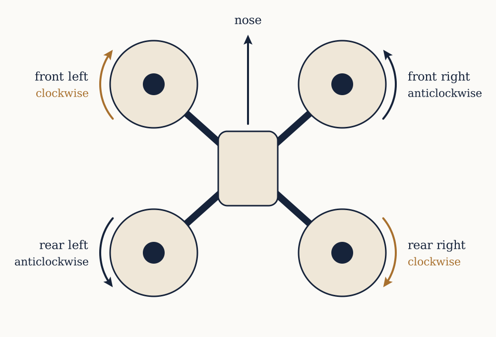
The quadcopter cancels it for free by spinning two propellers clockwise and two counter-clockwise, arranged so that the two of each kind sit on opposite corners. The reaction torques then come in two equal and opposite pairs, and their sum is zero, so a quadcopter with all four motors at equal speed feels no net twist and holds its heading. This is the single most important fact about the layout, and it is why the propellers are not interchangeable: a clockwise propeller is a mirror image of a counter-clockwise one, and fitting the wrong handedness makes a motor push its air the wrong way. Getting one of the four backwards is the classic first-build mistake, and the craft answers it by flipping the instant it leaves the ground.

That the torques cancel at equal speed also hands over a control, which the next lesson develops in full. Speed the clockwise pair up and slow the counter-clockwise pair down by the same amount, and the total thrust is unchanged, the craft neither rises nor falls, but the torques no longer cancel and the machine turns on the spot. The same trick of unbalancing what was balanced, applied to thrust across the front and back or the left and right, is how it leans and flies in a direction. A quadcopter has no rudder, no ailerons and no swashplate. It has four numbers, the four motor speeds, and every motion it makes is some combination of raising all of them and tilting the balance between them.

What holds it there

Nothing in this lesson keeps the craft level on its own. Four propellers making equal thrust hold height and heading, but the balance between them is a knife edge: a breath of wind, a slightly heavier battery on one side, a motor a few per cent stronger than its neighbour, and the craft tips. A helicopter can be flown by a skilled pilot because its dynamics are slow enough for a human to correct. A small quadcopter cannot, because it tips faster than a person can react, on the order of tenths of a second. What makes it flyable is a computer reading a rotation sensor hundreds of times a second and nudging the four motor speeds to hold the craft where it was told to be. That loop, the sensor and the controller, is as much a part of why a quadcopter stays up as the propellers are, and most of the second half of this course is about it.

For now the picture is complete enough to build on. Weight sets the thrust each propeller must make, the thrust to weight ratio decides whether the craft merely hovers or truly flies, the fourth power law says a larger propeller is worth far more than a faster small one, and the two-and-two arrangement of spin directions is what lets the machine hold its heading and turn at will. The next lesson turns those four motor speeds into the three rotations a pilot actually commands.
Roll, pitch, yaw, and the mixer

A pilot of a quadcopter has four levers to pull, and it is worth naming them before naming the motors, because the whole trick of flying the machine is turning one set into the other. The four commands are throttle, meaning climb or descend; pitch, tilting the nose down or up; roll, tilting to the left or right; and yaw, turning to face a new direction while staying level. Any flight, however wild, is a changing recipe of those four. The four motors know nothing of them. Each motor makes a thrust and a reaction torque, and the job of the mixer is to translate a pilot's four commands into four motor speeds, continuously, so that asking for more roll leaves height and heading untouched.

Four motors, four independent things

Label the motors by corner. In the common X layout the craft flies with an arm pointing forward-left, forward-right, back-left and back-right, and the propellers alternate in spin direction so that diagonal pairs match. Each motor contributes to all four commands at once, with a sign that depends on where it sits and which way it turns.

Throttle is the easy one: to climb, speed up all four equally. The thrusts rise together, their sum exceeds the weight, and the craft rises without tilting, because four equal increases stay balanced. This is the common part of every motor's command, the part that does not care about geometry.

Pitch and roll work by front-to-back and left-to-right imbalance. To pitch the nose down, speed up the two rear motors and slow the two front ones by the same amount. The extra thrust at the back and the reduced thrust at the front make a couple that tips the nose down, while the total thrust, and therefore the height, barely changes because what was added at the back was taken from the front. Roll is the identical idea rotated ninety degrees: speed up one side, slow the other, and the craft leans. In both cases the key is that the change is antisymmetric, a plus on one side and an equal minus on the other, so it produces a pure rotation and disturbs nothing else.

Yaw is the subtle one, and it is where the two spin directions earn their keep a second time. To turn right without leaning or climbing, speed up the two motors that spin one way and slow the two that spin the other, by equal amounts. The total thrust is unchanged, so height holds. The thrust imbalance is diagonal and cancels in both the pitch and roll directions, so the craft stays level. But the reaction torques no longer cancel: the sped-up pair now drags the air harder than the slowed pair, the net reaction twists the frame, and the craft rotates about its vertical axis. Yaw is commanded through torque, not thrust, which is why it is always the weakest and slowest of the three rotations, and why a quadcopter yaws far less crisply than it rolls.

The mixer as four sums

All of this is captured by a table of signs, one row per motor, one column per command, and the motor's speed command is throttle plus the signed contributions of pitch, roll and yaw:

Mi=T+aiP+biR+ciY

Here T is throttle, P, R and Y are the pitch, roll and yaw commands, and the coefficients ai, bi, ci are each +1 or -1 according to the corner and spin of motor i. A front motor gets -1 for a nose-down pitch and a rear motor +1; a left motor and a right motor get opposite roll signs; a clockwise motor and a counter-clockwise motor get opposite yaw signs. The pattern of signs is fixed by the geometry and never changes in flight. Flying the craft is nothing more than feeding four numbers into these four sums, thousands of times a second.

Example. A quadcopter hovers with every motor at a throttle value of 1500, on a scale where 1000 is off and 2000 is full. The pilot pushes for a small nose-down pitch worth 80 units, with no roll or yaw. What are the four motor commands?

The two front motors take 1500-80=1420 and the two rear motors take 1500+80=1580. The average is still 1500, so the total thrust and the height are unchanged, and the craft rotates nose-down until the pilot centres the stick.

Now you. From the same 1500 hover, the pilot commands a right roll of 60 units and nothing else. The right side motors should slow and the left side speed up. What are the left and right motor values?

Answer

The two left motors go to 1500+60=1560 and the two right motors to 1500-60=1440. The craft leans right, height held.

Saturation, and why a big command steals from the others

The sums have a ceiling and a floor. A motor cannot be commanded above full or below off, so once a motor is already near 2000, asking for more pitch cannot make it climb further, and the mixer has run out of room. This is motor saturation, and it is the reason a quadcopter at full throttle can barely steer: there is no headroom left to add to the motors that a roll would need. Good flight controllers handle saturation by pulling the whole throttle down a little when a rotation command would otherwise clip a motor, sacrificing a touch of height to keep the craft steerable, on the sound principle that a craft that will not turn is more dangerous than one that sags a few centimetres. It is the same reserve argument as the thrust to weight ratio in the previous lesson, now seen from inside the mixer: flying near the ceiling leaves nothing for control.

Why the craft still needs a brain

The mixer is a fixed piece of arithmetic. It faithfully turns a pitch command into the right motor imbalance, but it has no idea whether the craft is actually level. If the pilot commands zero pitch and zero roll, the mixer holds all four motors equal, and a perfectly balanced craft in still air would stay put. No real craft is perfectly balanced and no real air is still, so left to the bare mixer the machine drifts and tips within a second. What closes the gap is a controller that measures the craft's actual rotation and generates the pitch, roll and yaw commands itself, correcting error rather than obeying a stick. The mixer sits underneath that controller and never changes; the controller above it is the subject of the sensing and control lessons later in the course. For now the important result is the division of labour. The mixer answers the question of how to produce a wanted rotation from four motors. It says nothing about what rotation is wanted, and that second question is the harder half of making a quadcopter fly.

Propellers and momentum theory

The first lesson quoted a scaling law for thrust and promised a derivation. The derivation is one of the most useful pieces of physics in the whole subject, because it does not just give a formula, it explains why a quadcopter that flies for twenty minutes must be built around large propellers turning slowly, and why the racing habit of small propellers turning fast is paid for in flight time. The model is called momentum theory, and it replaces the messy reality of spinning blades with a single idealised disc.

The actuator disc

Picture the propeller as an infinitely thin disc of area A=πR2, where R is the blade radius, that does one thing: it accelerates the air passing through it, pushing it downward. Far above the disc the air is still. As it approaches it speeds up, at the disc it is moving down with an induced velocity vi, and far below it has reached a final velocity w. Thrust is the rate at which the disc adds downward momentum to the air, and by conservation of momentum that rate is the force pushing back up on the disc.

The mass of air passing through the disc each second is m˙=ρAvi, the density times the area times the speed at the disc. The air enters with no downward speed and leaves far below with speed w, so the momentum added per second, which is the thrust, is

T=m˙w=ρAviw

A short argument from energy, which we take on trust here, shows that the air reaches half its final speed by the time it crosses the disc, so w=2vi. Substituting gives the central result of momentum theory:

T=2ρAvi2vi=T2ρA

The induced velocity needed to make a given thrust falls as the disc area rises. A larger propeller makes the same thrust while throwing a larger mass of air more gently, and that gentleness is exactly what saves energy, as the next section shows.

Why hovering is expensive

The power the propeller must deliver to the air is the thrust times the speed of the air at the disc, P=Tvi. Substituting the induced velocity gives the ideal hover power:

P=Tvi=TT2ρA=T3/22ρA

Two features of this expression govern flight time. First, power grows as thrust to the power of three halves, faster than thrust itself, so a craft that is fifty per cent heavier needs about eighty per cent more power to hover, and weight is punished more than linearly. Second, and this is the design lever, power falls as the square root of the disc area. Double the disc area, by making the propellers larger, and the hover power drops by a factor of 2, about thirty per cent, for the same thrust. This is the physics behind the endurance rule: a long flight wants the largest propellers the frame can carry, turning as slowly as they can while still making the weight in thrust. A racer accepts terrible hover efficiency in exchange for the light, small, fast propellers that give instant response.

Example. A 500 g quadcopter hovers on four 5 inch propellers, radius about 0.064 m, so each disc has area A=π(0.064)2=0.0129 m². Each propeller carries a quarter of the 4.9 N weight, so T=1.23 N. Taking ρ=1.225 kg m⁻³, what is the induced velocity and the ideal power per motor?

vi=1.23/(2×1.225×0.0129)=38.9=6.24 m s⁻¹. The ideal power is P=Tvi=1.23×6.24=7.7 W per motor, so about 31 W for the craft. Real propellers are far from ideal, so the true figure is two to three times this, but the scaling is exact and it is the scaling that matters.

Now you. The same craft is rebuilt on 7 inch propellers, radius about 0.089 m, disc area 0.0249 m², same thrust per motor. Find the new induced velocity and ideal power per motor.

Answer

vi=1.23/(2×1.225×0.0249)=20.2=4.49 m s⁻¹, and P=1.23×4.49=5.5 W. Larger disc, gentler air, less power for the same lift.

From the disc back to the scaling law

Momentum theory as written involves the induced velocity, which is not something a builder chooses directly. What a builder chooses is the diameter D=2R and, through the motor, the rotation rate n. A blade element moves through the air at a speed proportional to nD, and the thrust a blade makes rises with the square of its speed and with its area, which is proportional to D2. Collecting the factors gives the static thrust law of the first lesson:

Tρn2D4

and the same reasoning applied to power gives Pρn3D5. These two are how propellers are actually specified in practice, folded into a single number each. Manufacturers publish a thrust coefficient and a power coefficient, and the constants that turn the proportionalities into equalities absorb the blade shape, the number of blades and the pitch. The lesson to carry forward is the exponents. Thrust goes as the square of speed and the fourth power of size; power goes as the cube of speed and the fifth power of size. Speed is cheap in thrust and expensive in power, which is the same statement as before that hovering fast is wasteful.

Pitch, the second dimension of a propeller

A propeller is sold by two numbers, its diameter and its pitch, written together as 5x4.3 or 7x4. The pitch is the distance the propeller would advance in one turn if it moved through the air like a screw through wood, and it sets how aggressively the blade bites. A high pitch propeller moves more air per turn and reaches a higher top speed, but it demands more torque and draws more current, and it stalls more readily when the craft is climbing hard. A low pitch propeller is gentle, efficient and forgiving. Pitch is the fine adjustment that diameter is the coarse one: pick the diameter for the class of craft, then the pitch to trade top speed against efficiency and load. A propeller too aggressive for its motor overheats the motor and the electronics, which is the mechanism behind a whole category of build failures, and the power law is the warning: pitch pushes on the same cubic power curve that size does.

What the model leaves out

Momentum theory is an idealisation and knows nothing of the blade itself. It assumes the air arrives smoothly, ignores the swirl the blade leaves behind, and treats the disc as loss-free, so its power figures are a floor that no real propeller reaches. The ratio of the ideal power to the real power is a propeller's figure of merit, typically around 0.7 for a good small propeller, and it is where blade design, tip losses and the air's viscosity all hide. None of that changes the exponents, which is why the model earns its place: it will not predict a propeller's thrust to the gram, but it explains, correctly and for good, why the endurance machine and the racer look so different, and why the single most effective thing a builder can do for flight time is fit the biggest propellers the frame will take.

Brushless motors

The propeller lessons treated the rotation rate as a free choice. It is not free; it is delivered by a motor, and the kind of motor a quadcopter uses is worth understanding in its own right, because its behaviour sets the voltage of the battery, the current the wiring must carry, and the marriage between motor and propeller that a good design lives or dies by. Almost every multirotor uses a brushless DC motor, and the name is best read as a correction of the older brushed kind it replaced.

Why brushless

A brushed motor spins because a rotating coil is fed current through sliding contacts, the brushes, that flip the current's direction twice per turn to keep the push going. The brushes work but they wear, they spark, and they limit the speed and the life of the motor. A brushless motor removes them by turning the machine inside out. The coils are fixed to the stationary part, the stator, and the permanent magnets are on the spinning part, the rotor. Nothing rubs. The catch is that something must now do the brushes' old job of switching the current at the right moments from outside, and that something is the electronic speed controller of the next lesson. The motor and its controller are one system, and neither makes sense alone.

Multirotor motors are almost all outrunners, meaning the rotor is the outer bell that spins, wrapped around a stationary inner stator. The bell carries the magnets and the propeller bolts to its top. This layout puts the magnets at a large radius, which gives high torque at modest speed, exactly what a propeller wants, in contrast to the inrunner arrangement used where raw speed matters more than torque.

Three phases and the rotating field

The stator's coils are wired in three groups, the three phases, usually called A, B and C. Driving current into the phases in the right repeating sequence makes the magnetic field of the stator point in a direction that steps around the circle, and the rotor's permanent magnets chase that direction, so the bell turns. This is why a brushless motor has three wires and not two: two would give a field that only flips back and forth, while three give one that rotates. The controller's whole task is to energise the three phases in the correct order and at the correct moments, an action called commutation, and it is doing electronically and hundreds of times a second what the brushes did mechanically.

The rotor does not turn once for every cycle of the phases. It carries several pairs of magnetic poles, commonly seven pairs on a small multirotor motor, and the field must cycle once for each pole pair to move the rotor one full turn. The electrical frequency the controller produces is therefore the pole pairs times the mechanical rotation rate, which is why these motors need such fast switching: a motor with fourteen poles spinning at thirty thousand rpm asks the controller to run its phases through three and a half thousand electrical cycles a second.

The Kv rating

The one number that a builder chooses a motor by is its Kv, the velocity constant. It states how many rpm the unloaded motor turns for each volt applied, in rpm per volt. A 2400 Kv motor on a fully charged four cell battery, about 16.8 V, spins near 2400×16.8=40{,}000 rpm with no propeller. Under load it turns slower, but Kv still sets the ballpark and, crucially, it sets how motor and battery must be matched. A high Kv motor spins fast on a low voltage and suits small propellers; a low Kv motor spins slowly and suits large ones. Choosing a high Kv motor and a large propeller together is a classic destructive mismatch, because the motor tries to spin the big propeller fast, the current soars, and the motor or the controller burns.

Kv has a hidden partner. The same construction that gives a high Kv gives a low torque constant, the torque produced per amp of current, and the two are reciprocal: Kt1/Kv once consistent units are used. A motor wound for high speed per volt produces little torque per amp, and a motor wound for high torque per amp turns slowly per volt. There is no winding that gives both, which is the electrical face of the same trade the propeller makes between speed and load. Fast and gentle, or slow and strong, is a choice made once in the motor's copper and never escaped.

Example. A builder has a 2207 motor rated at 1800 Kv and wants a rough top speed on a fully charged six cell battery, about 25.2 V. Ignoring load, what is it?

1800×25.2=45{,}360 rpm unloaded. A propeller loads it down to perhaps sixty to seventy per cent of that in the air, so a working figure near 28,000 to 32,000 rpm, which is a sensible speed for the 5 inch propellers a 2207 motor is built for.

Now you. The same 2207 frame is offered in a 2400 Kv winding. On a four cell battery, about 16.8 V, what is the unloaded top speed, and is that higher or lower than the 1800 Kv motor on six cells above?

Answer

2400×16.8=40{,}320 rpm unloaded, lower than the 45,360 of the 1800 Kv on six cells. Higher Kv on lower voltage often lands near the same place, which is why builders can reach a target speed from either direction and then choose by current and efficiency.

Reading a motor's size

Motors are named by a four digit number like 2207 or 2306, and it is not arbitrary. The first two digits are the stator's diameter in millimetres and the last two its height, so a 2207 has a stator 22 mm across and 7 mm tall. The stator is where the copper and the iron that make torque live, so its volume, not the bell's size, is what sets how much work the motor can do and how much heat it can shed. A taller or wider stator makes more torque and runs cooler at a given load, at the cost of weight. The pairing of stator size with propeller size is the heart of a build: a 22 by 7 stator is the standard partner for 5 inch propellers, a larger stator for larger propellers, and the Kv is then chosen to hit the wanted speed on the chosen battery voltage. Get the three to agree, stator size to propeller, Kv to voltage, and voltage to the current the wiring can carry, and the propulsion system is settled. The current itself, and the controller that meters it, are the next two lessons.

ESCs and turning DC into three phases

The previous lesson left a motor that cannot run on its own, because the coils need their current switched in a repeating sequence timed to the rotor's position, and there are no brushes to do it. The electronic speed controller, the ESC, is what does it. One sits at the base of each arm, wired to the battery on one side and to the three motor phases on the other, and it is a small computer with power electronics attached. Understanding it removes most of the mystery from a quadcopter's electrical faults, because the ESC is where the battery's raw direct current becomes the three timed phases the motor turns on.

Six switches and a sequence

The heart of an ESC is six power transistors, MOSFETs, arranged as three half-bridges, one per phase. Each phase wire can be connected by its pair of transistors either up to the battery positive or down to the battery negative, or left floating. With three phases each in one of these states, the controller can drive current from any phase to any other. Commutation in the simplest scheme, called six-step or trapezoidal, energises two phases at a time and leaves the third floating, then steps to the next pair, and so on through six steps that complete one electrical cycle. At each step the stator field points in a fixed direction, the rotor swings toward it, and just before it arrives the controller steps to the next pair so the field keeps leading. Done fast and in order, the six steps become a smoothly turning field and a smoothly turning motor.

Knowing where the rotor is, without a sensor

The steps must be timed to the rotor, so the controller has to know the rotor's angle. Some motors carry position sensors, but multirotor ESCs are almost all sensorless, and they read the rotor from the motor itself. The trick is the floating phase. A permanent magnet moving past a coil induces a voltage in it, the back-EMF, and while two phases are driven the third is left floating precisely so the controller can measure the back-EMF on it. The moment that voltage crosses the midpoint, the zero crossing, tells the controller exactly where the rotor is, and it schedules the next commutation step a fixed fraction of a step later. The motor is its own position sensor, read on the wire that happens to be idle.

This is also why a brushless motor can stutter or fail to start. At rest and at very low speed there is no back-EMF to read, so the controller has to guess the first few steps blindly, nudging the rotor until it spins fast enough to generate a signal it can lock onto. A motor that twitches instead of starting, or that stalls under sudden load, is usually a controller that has lost the back-EMF and its place in the sequence. It is the sensorless scheme showing its one weakness, at the low speeds where a quadcopter fortunately spends little time.

Setting the speed

Commutation sets the timing; something else must set the speed. The controller varies the motor's speed by switching the driven phases on and off very fast, tens of thousands of times a second, and varying the fraction of time they are on. This is pulse width modulation, and the on fraction, the duty cycle, sets the average voltage the motor sees and hence its speed. A throttle of half is the controller holding the phases on for half of each tiny interval. The motor's inductance smooths the chopped voltage into a steady current, so the motor feels an average and not the switching itself, though the switching is audible as the characteristic whine.

Example. A four cell battery reads 15.0 V under load. The flight controller commands 40 per cent throttle. Ignoring losses, what average voltage does the motor see, and if the motor is 1800 Kv, what unloaded speed does that imply?

At 40 per cent duty the average is 0.40×15.0=6.0 V. At 1800 Kv the unloaded speed is 1800×6.0=10{,}800 rpm. Under a propeller's load the real speed is lower, but the duty cycle is the throttle's grip on the motor.

Now you. The same setup is commanded to 75 per cent throttle on a 15.0 V pack. What average voltage reaches the motor, and the unloaded speed at 1800 Kv?

Answer

0.75×15.0=11.25 V, and 1800×11.25=20{,}250 rpm unloaded.

How the flight controller talks to the ESC

The flight controller sends each ESC a throttle command hundreds or thousands of times a second, and how it sends it has evolved. The oldest scheme borrows the servo signal of radio control, a pulse whose width from one to two milliseconds means off to full, updated only fifty to five hundred times a second. It works but it is slow and analog, so a little electrical noise shifts the pulse and the throttle. The modern replacement, DShot, sends the throttle as a digital number in a short burst of bits, immune to noise, checksummed so a corrupted command is discarded rather than obeyed, and fast enough to update every control loop. Digital telemetry can even flow back the other way, the ESC reporting the motor's real rpm and temperature. Choosing DShot over the old pulse scheme is one of the easy correct decisions in a modern build, and it removes a whole class of twitchy throttle faults.

Current, heat and the rating that matters

The number printed largest on an ESC is its current rating in amps, and it is the ceiling on how hard the motor may be driven. Every transistor has a small resistance, and current through a resistance makes heat at a rate of I2R, that square again, so doubling the current quadruples the heating in the ESC. Push a motor and propeller that draw more current than the ESC is rated for and the transistors overheat and fail, often taking the motor's timing with them. This is the same I2R that governs the wiring in the next lesson, and it is the single most common way a propulsion system destroys itself: an aggressive propeller, a high Kv motor, and an ESC without the current headroom to survive them. Size the ESC above the worst current the motor and propeller will ever draw, with margin, and it becomes the reliable servant it should be, faithfully turning a throttle number into a spinning field.

The power system, battery to current

A quadcopter is a machine for converting stored chemical energy into moving air, and the store is a lithium polymer battery. Its properties decide the voltage the whole craft runs at, the current the wiring must survive, and the few minutes of flight the pilot gets. The power system is unglamorous and it is where a large share of builds fail, through a battery that cannot deliver the current, a wire too thin for it, or a connector that melts. The physics is the ohm's law and the I2R loss of any electrical course, applied to a craft that pulls a hundred amps from a pack the size of a paperback.

Cells, voltage and the S number

A lithium polymer cell has a nominal voltage of 3.7 V, sitting at 4.2 V when fully charged and considered empty at about 3.5 V under load. One cell alone is too little to run a motor usefully, so cells are wired in series to add their voltages, and the count is quoted as an S number: a 4S pack is four cells in series, nominally 4×3.7=14.8 V and 16.8 V fresh off the charger. The S number is the first choice in a build because it sets the voltage every other component must match. A given motor's speed is its Kv times this voltage, so moving from 4S to 6S raises the speed of the same motor by half, which is why the hobby drifted from 4S toward 6S: higher voltage reaches the same power at lower current, and lower current is easier on everything downstream.

Capacity, C rating and the current a pack can give

Two more numbers finish the battery. The capacity, in milliamp hours, is how much charge it holds: a 1500 mAh pack can in principle give 1500 mA for an hour, or 1.5 A, or proportionally more current for less time. The C rating is how fast it may be discharged safely, as a multiple of the capacity. A 1500 mAh pack rated at 100C can give 100×1.5=150 A, and a pack asked for more than its C rating sags hard, heats, and ages fast. The two multiply into the maximum safe current, and matching that to the craft's real draw is the point of the specification. A racing quad that pulls 120 A in a punch needs a pack whose capacity times C rating clears 120 A with margin, or the pack becomes the weak link.

Under load the voltage droops below its resting value, an effect called sag, because the pack has its own small internal resistance and the current through it drops voltage inside the cell. A pack at 16.8 V resting might sag to 14 V during a hard climb, and since motor speed follows voltage, the craft has less power exactly when it is asking for most. A tired or under-rated pack sags more, and heavy sag that pulls a cell below about 3.3 V under load is what damages lithium cells and starts fires. Respecting the C rating and landing before the pack is flat are the two habits that keep it safe.

Example. A quadcopter hovers drawing about 18 A from a 4S pack and can pull 90 A at full throttle. It uses a 1300 mAh pack. What C rating does it need for the full-throttle draw, and roughly how long can it hover?

For 90 A from 1.3 Ah the pack must be rated at least 90/1.3=69 C, so a 75C or 100C pack. For hover, a rough flight time is the usable capacity over the current: taking 80 per cent of 1.3 Ah as usable, 0.8×1.3/18=0.058 h, about 3.5 minutes. Racers fly short; the endurance rules of the propeller lesson are how camera craft reach twenty.

Now you. A camera drone hovers at 9 A on a 6S 5000 mAh pack. Using 80 per cent of the capacity, roughly how long can it hover?

Answer

0.8×5.0/9=0.44 h, about 27 minutes. Large capacity and gentle current is the endurance recipe, at the cost of carrying a heavy pack.

Power, current and why voltage is chosen high

Electrical power is voltage times current, P=VI. A craft that needs 300 W to hover can take it as 20 A at 15 V or as 12 A at 25 V, and the same power at higher voltage means lower current. This is the entire reason to prefer a higher S number: the losses that plague a power system nearly all grow with current, not with power, so delivering a given power at higher voltage and lower current makes the wiring, the connectors and the ESCs all run cooler. The motor does the same work either way; it is the delivery that gets cheaper.

Wiring, connectors and the square law again

Current has to travel from the pack to the four ESCs, and every centimetre of wire and every connector has a small resistance that turns some of the power into heat at the rate I2R. That square is why the main leads and the battery connector are the fattest wires on the craft: at 90 A even a few milliohms of resistance wastes several watts and warms the wire noticeably. A wire too thin for the current sags the voltage further, heats, and in the worst case melts its insulation and shorts. Wire is sized by gauge to the current it will carry, thicker for the main battery leads and the arms of a high current build, and the battery connector, commonly an XT60 or XT30 by current, is chosen the same way. Many builds route the pack through a power distribution board that fans the one battery input out to the four ESCs and the flight controller, often with a capacitor across the input to absorb the voltage spikes the switching ESCs throw back down the leads. Those spikes are real and they damage electronics; the low-ESR capacitor near the battery is cheap insurance that a surprising number of builds skip and regret.

Reading the system as one loop

The power system is a chain and it is only as strong as its weakest current-carrying link. The pack must be able to give the peak current without sagging past the cell's safe floor, the connector and wire must carry that current without overheating, the ESC must be rated above it, and the motor and propeller set what that current is. Trace the worst case current from propeller back to pack and check every link against it, and the craft flies for its whole flight instead of failing on the first hard throttle. Get one link wrong, a pack under-rated for the draw or a wire too thin for it, and the failure is not subtle: it is voltage sag and heat, and at these currents heat is measured in melted plastic. The sensing and control that make the craft flyable, which the rest of the course covers, all assume this loop is sound.

Sensing rotation, the IMU

The mixer lesson ended on a promise: the craft needs something to decide what rotation is wanted, because left to a bare mixer it tips within a second. That something begins with measurement. Before a controller can hold the craft level it must know how the craft is oriented and how fast it is turning, and both come from a single component the size of a grain of rice, the inertial measurement unit, or IMU. It contains two sensors, a gyroscope and an accelerometer, and the art of using it is knowing exactly what each one can and cannot tell you.

MEMS, or machines etched in silicon

Both sensors are micro-electro-mechanical systems, tiny mechanical structures etched into silicon alongside the circuit that reads them. Inside is a suspended mass a fraction of a millimetre across, held on silicon springs, that moves a little when the chip accelerates or rotates, and the movement is read as a change in electrical capacitance. That a real, if microscopic, mass swinging on real springs is what a flight controller feels the world through is worth keeping in mind, because the sensor's limits are the limits of a small noisy spring and mass, not of an abstract number.

The gyroscope measures rate, not angle

The gyroscope measures the rate at which the craft is rotating, in degrees per second, about each of the three axes. It is the more important of the two for flight, because rotation rate is fast and immediate: the moment a gust starts to tip the craft, the gyro reports the turning, with almost no delay and little sensitivity to vibration or to the craft's motion through the air. A flight controller reads the gyro thousands of times a second and it is the gyro, above all, that lets the machine catch a tip before a human could see it.

The gyroscope's weakness is that it measures rate and not angle. To know the craft's actual tilt from a gyro you must add up, or integrate, the rate over time, and any small constant error in the rate, a bias, accumulates without bound. A gyro reading half a degree per second too high, sitting perfectly still, will after one minute claim the craft has rotated thirty degrees. This creeping error is drift, and it is the defining flaw of a gyroscope: excellent for how fast the craft is turning right now, useless on its own for which way is up after a while.

The accelerometer feels down, when it can

The accelerometer measures acceleration, but for a craft sitting still its most useful reading is gravity. A stationary accelerometer feels a steady 1 g pulling down, and from the way that 1 g is split across its three axes the controller can work out which way the chip is tilted. An accelerometer flat and level reads all its gravity on the vertical axis; tip it and some of that gravity appears on the horizontal axes, and the ratio gives the tilt angle directly, with no integration and so no drift. Where the gyro is blind to absolute tilt, the accelerometer sees it.

The accelerometer's weakness is the mirror of the gyro's. It cannot tell gravity from any other acceleration, because it measures their sum. A quadcopter in flight is shaking from propeller vibration and accelerating as it manoeuvres, and both add to the gravity it is trying to read, so the raw accelerometer signal in flight is a noisy mess in which the steady 1 g of gravity is buried. Trusted alone in flight it would report a tilt that jerks with every vibration and every change of speed. It is reliable about down only when the craft is still or moving smoothly, which is exactly when the gyro is least needed.

Example. A gyroscope has a bias of 0.3 degrees per second that has not been calibrated out. The craft sits motionless on the bench. If the controller estimates tilt by integrating the gyro alone, what tilt error has built up after two minutes?

Two minutes is 120 s, so the accumulated error is 0.3×120=36 degrees. The craft has not moved, yet a gyro-only estimate now believes it is tilted well past level. This single number is why a gyro is never integrated on its own for attitude.

Now you. An accelerometer lies with its measured gravity split as 0.5 g on one horizontal axis and about 0.87 g on the vertical axis. Roughly what tilt angle does that correspond to?

Answer

The tilt is arctan(0.5/0.87)=30 degrees. The horizontal component of gravity grows with the sine of the tilt, so reading it back gives the angle, no integration involved.

Bias, noise and the need for calibration

Neither sensor is perfect even at rest. Both carry a small fixed offset, the bias, and a jittery random component, the noise. The bias is why a flight controller asks to sit still on a level surface at power-up: it measures each sensor's reading while nothing is moving and subtracts it thereafter, which is calibration, and it is why a craft armed on a slope or while being carried flies out of trim. The noise is why the raw signals are filtered before use, a balance between smoothing out the jitter and not adding delay, since a filtered signal is always a little late and lateness in a fast control loop causes its own trouble. Temperature shifts the bias too, which is why a good controller recalibrates and why a cold craft can behave differently for its first minute.

Two flaws that cancel

The picture that emerges is two sensors with opposite strengths. The gyroscope is fast and drift-prone: right about rate, slowly wrong about angle. The accelerometer is slow and drift-free but noisy: right about angle on average, useless from moment to moment in flight. Neither alone can hold a craft level. The gyro-only estimate drifts away over seconds; the accelerometer-only estimate shakes to pieces. The resolution is to use each for the band it is good at, the gyro for the fast changes and the accelerometer for the slow truth of where down is, and to blend them so the drift of one is corrected by the other. That blend is the subject of the next lesson, and it is the quiet piece of mathematics that turns two flawed sensors into one trustworthy sense of which way is up.

Estimating attitude by fusing the sensors

The last lesson set up a puzzle with an obvious shape. The gyroscope is right about how fast the craft is turning but drifts when you integrate it into an angle. The accelerometer is right about which way is down on average but shakes too much to trust from moment to moment. Each is good on exactly the timescale the other is bad on, and that is the opening for a fix: use the gyro for the fast changes and the accelerometer for the slow truth, and blend them so that the drift of the one is continually pulled back by the other. The classic blend is the complementary filter, and it is one line of arithmetic that a small flight controller can run thousands of times a second.

The complementary filter in one equation

Suppose the controller holds an estimate of the tilt angle, θ, and updates it every small time step Δt. Two new pieces of information arrive each step: the gyroscope's rate ω, which predicts a new angle by integration, and the accelerometer's own direct estimate of tilt, θacc. The complementary filter combines them as

θα(θ+ωΔt)+(1-α)θacc

with α a constant just below one, often about 0.98. Read the two pieces. The first term takes the old angle, adds the gyro's motion over this step, and keeps 98 per cent of it: this is the fast, responsive part, the integrated gyro, and on its own it would drift. The second term nudges the estimate 2 per cent of the way toward whatever the accelerometer currently says down is: this is the slow correction that cancels the drift. Over a fraction of a second the gyro dominates and the estimate tracks quick motion cleanly; over many seconds the small accelerometer pull wins and holds the estimate locked to true level. Each term covers the band the other cannot, which is why it is called complementary.

The single knob α sets where the handover happens. Its time constant is roughly τ=αΔt/(1-α), the timescale below which the gyro is trusted and above which the accelerometer takes over. Push α toward one and the filter leans harder on the gyro, smoother but slower to correct drift; pull it down and it trusts the shaky accelerometer more, quicker to level but jumpier. The right value trusts the gyro over the seconds of a manoeuvre and lets the accelerometer own the minutes.

Example. A filter runs at Δt=0.001 s with α=0.98. Roughly what is its time constant, and what does that mean?

τ=0.98×0.001/(1-0.98)=0.00098/0.02=0.049 s. Below about 50 milliseconds the estimate follows the gyroscope; above it, the accelerometer steadily corrects any drift. So a fast flick is tracked by the gyro and a slow lean is anchored by gravity.

Now you. The same 0.001 s loop is set to α=0.995. What is the time constant now, and is drift corrected faster or slower than before?

Answer

τ=0.995×0.001/0.005=0.199 s, about four times longer. The filter trusts the gyro further, so it is smoother but corrects drift more slowly.

Why gravity cannot give heading

The accelerometer anchors two of the three rotations and only two. It reads the direction of gravity, which fixes how the craft is tilted in pitch and roll, but gravity points the same way whichever direction the craft is facing, so it says nothing about heading, the yaw angle. Spin a level craft on the spot and every accelerometer axis reads exactly as before. The gyro can measure the rate of that spin and integrate it, but with nothing to correct against, the yaw estimate drifts freely, and this is why a quadcopter's heading wanders over a long hover while its level stays true. To pin heading down needs a third sensor, a magnetometer, which reads the Earth's magnetic field the way the accelerometer reads gravity and gives an absolute compass direction to correct the yaw drift against. Many small racing craft simply do without, accepting slow heading drift because the pilot is steering by sight, while any craft that must hold a heading or return home carries one, and pays for it with sensitivity to the magnetic mess of its own motor currents.

Angles, and the trap of three of them

Describing an orientation by three angles, pitch, roll and yaw, is intuitive and is how a pilot thinks, but it hides a defect that bites when a craft points straight up or flips fully over. At certain orientations two of the three angles line up and control one and the same rotation, so a degree of freedom is lost and the maths becomes singular, a failure called gimbal lock. It is why acrobatic flight controllers do not store attitude as three angles internally but as a quaternion, a four-number object that represents any orientation without a singular point anywhere. Quaternions are harder to picture and the arithmetic is less transparent, but they never jam, and a craft that must fly through vertical and inverted has to use them. The three angles remain the language the pilot and the tuning screens speak; the quaternion is the language the controller keeps its own state in.

The estimate the rest of the craft depends on

What the fusion produces, whether by a plain complementary filter or by its more elaborate cousin the Kalman filter that carries an explicit model of the sensor noise, is a single trustworthy estimate of the craft's attitude and rotation rate, updated every control cycle. It neither drifts like the raw gyro nor shakes like the raw accelerometer. Everything the flight controller does downstream leans on it. The controller of the next lesson compares this estimate against what the pilot asked for and works out the correction, and the mixer turns that correction into motor speeds. A quadcopter is in the end a fast loop from this estimate to those four motors, and the quality of the estimate sets the ceiling on how well the craft can be made to fly. A noisy or laggy attitude estimate cannot be rescued by any amount of tuning downstream, which is why clean sensor mounting and honest fusion come before the control loop, not after it.

The control loop, PID and stabilization

Everything so far has built the two halves that the mixer lesson kept apart. Below sits the machinery that turns a wanted rotation into motor speeds. Above sits the sensing that reports the craft's actual rotation. The piece between them, the one that decides what correction to make, is the control loop, and it runs the same small calculation thousands of times a second: compare where the craft is with where it should be, and push the motors to close the gap. The calculation almost every multirotor uses is the PID controller, three terms whose initials name what each one does.

Error, and the idea of feedback

Start with a single axis, say roll. The pilot commands a wanted roll rate, the setpoint. The gyroscope reports the actual roll rate, the measurement. Their difference is the error:

e=setpoint-measurement

A controller's whole job is to drive that error to zero by acting on the motors, and then to keep it there as gusts and imbalances try to reopen it. This is feedback: the output is measured and fed back to correct the input, continuously, so the craft chases its target rather than being aimed once and hoping. The PID controller builds its correction from the error in three ways.

Proportional, the present

The proportional term reacts to the error right now. It multiplies the current error by a gain and pushes that hard:

uP=KPe

Big error, big push; small error, small push. On its own the proportional term does most of the work, but it has two flaws. Set the gain too low and the craft is sluggish, sagging under a gust because a small error produces only a feeble correction. Set it too high and the craft overshoots the target and comes back past it, over and over, a self-sustaining oscillation that shakes the airframe and, in the worst case, grows until the craft is uncontrollable. The proportional gain is the first thing a tuner sets and the loudest when it is wrong.

Integral, the past

The integral term adds up the error over time and corrects for the part that will not go away:

uI=KIedt

Its purpose is to kill a steady offset. Suppose the battery sits a little off-centre so the craft always wants to drift right, leaving a small persistent error the proportional term never quite clears, because a tiny error makes only a tiny push. The integral accumulates that small error until its sum is large enough to hold the craft true. It is the term that makes the craft settle exactly on target rather than near it. Its danger is lag and a fault called windup: because it responds to the accumulated past, too much integral makes the craft slow and wallowing, and if the motors saturate the sum can grow huge and take time to unwind, so real controllers limit it.

Derivative, the future

The derivative term watches how fast the error is changing and pushes against sudden movement:

uD=KDdedt

It is the damping. When the craft is racing toward its target the derivative sees the error shrinking fast and eases off early, so the craft arrives without overshooting, the way a careful driver lifts off the accelerator before the corner rather than at it. Derivative lets the proportional gain be pushed higher without oscillation, which makes the craft both crisp and stable. Its curse is noise: the derivative of a jittery signal is far jitterier, so a high derivative gain amplifies every vibration into motor twitch and heat, and this is why clean sensor mounting and filtering, from the earlier lessons, matter so much here. The derivative term is where a noisy craft punishes its builder.

The full correction is the sum, fed as the command into the mixer:

u=KPe+KIedt+KDdedt

Example. A rate controller has KP=0.5. At one instant the roll error is 40 degrees per second. What is the proportional part of the correction, in the controller's command units?

uP=0.5×40=20 units. If the error were only 5 degrees per second the proportional push would be 2.5 units, a tenth as much, which is the sense in which it answers the present in proportion.

Now you. With KP=0.5 and KD=0.02, the error is 10 degrees per second and is falling at 300 degrees per second per second. What are the proportional and derivative parts, and do they add or oppose?

Answer

uP=0.5×10=5. The error is falling, so its rate of change is -300, giving uD=0.02×(-300)=-6. The derivative opposes the proportional, easing off because the craft is already correcting fast, which is exactly its damping job.

Two loops, stacked

One PID controller running on rate gives what pilots call acro mode: the stick commands a rotation rate, and when centred the craft holds whatever attitude it is in, even inverted, which is what acrobatic and racing flight wants. To make the craft self-level, so that a centred stick returns it to flat, a second, slower PID is stacked on top. This outer angle controller takes the error between the wanted tilt and the estimated tilt from the fusion lesson and produces a wanted rate, which it hands down to the inner rate controller as its setpoint. The inner loop still does the fast work against the gyro; the outer loop steers the inner one toward level. This cascade, an angle loop commanding a rate loop, is how a quadcopter offers both a stable beginner mode and a free acrobatic one from the same machinery, by switching whether the outer loop is in charge.

Tuning, and why it is never finished

The gains are not universal. They depend on the craft's weight, its motors, its propellers and its stiffness, so every build is tuned, and tuning is the craft of raising each gain until just before it misbehaves and then backing off. Too much proportional and the craft oscillates at a fast buzz; too much derivative and it heats and twitches on noise; too much integral and it wallows and is slow to settle. The loop also has a speed, its loop rate, the number of times a second it runs, commonly several thousand on a modern controller, and a faster loop can hold a twitchier craft because it corrects sooner. Underneath the numbers the idea is fixed and worth carrying out of this course whole: measure the error, and answer its present with proportion, its past with the integral, and its future with the derivative. That single pattern stabilises not just a quadcopter but most of the machines that hold themselves steady, and a builder who understands it can tune by reasoning about what each term is failing to do rather than by turning knobs at random.

The frame, structures and 3D design

The frame is the part a newcomer thinks least about and an experienced builder respects most, because it is where the clean world of physics meets the messy one of materials, vibration and impact. It holds the four motors at the corners, carries the electronics in the middle, and takes every force the craft makes or suffers. A good frame is almost invisible in flight; a bad one corrupts the sensor readings, snaps in a minor crash, or shakes the video into uselessness. Designing one is a structures problem, and increasingly a 3D printing problem, because the parts that hold everything together are now routinely drawn in CAD and printed at home.

The loads a frame carries

Three kinds of force act on a frame. The first is thrust, the steady upward pull of each motor, which tries to bend each arm up at its tip like a diving board loaded at the end. An arm is a cantilever beam, fixed at the body and free at the motor, and a cantilever's deflection depends steeply on its length and its stiffness: a longer arm bends far more for the same force, which is one reason arms are kept as short as the propellers allow. The second load is vibration, the fast shaking from four propellers that are never perfectly balanced, running at tens of thousands of rpm. The third is impact, the sudden enormous force of a crash, which is the load that actually breaks frames, because a craft that flies at speed carries real kinetic energy and a hard stop dumps it all into the frame in a millisecond.

Why stiffness matters more than strength

A frame can be strong, able to bear a large steady load, and still be a poor frame if it is not stiff, meaning it barely flexes under load. Stiffness matters more than raw strength for a subtle reason that ties back to the sensing lessons. The IMU sits on the frame and measures the frame's motion, and it cannot tell the craft's true rotation from the frame flexing and ringing around it. A floppy frame has low resonant frequencies, the frequencies at which it naturally vibrates, and when a propeller's vibration matches one of them the frame rings like a bell, feeding a large false signal straight into the gyroscope. The control loop then reacts to vibration as if it were real motion, which the derivative term of the PID amplifies into motor twitch and heat, and the craft flies badly for a reason no amount of tuning can fully fix. A stiff frame pushes its resonances up high, out of the range the propellers excite and the control loop cares about, which is why builders prize stiffness and why the fix for a shaky craft is often mechanical, not a gain.

Carbon fibre, and the shape of the material

The material that dominates is carbon fibre composite, thin fibres of carbon set in a resin. It earns its place by having an enormous stiffness for its weight, several times that of aluminium per gram, which is exactly the property a frame wants: high stiffness with little mass to lift. It has one quirk that governs how it is used. The fibres are strong and stiff only along their length, so a sheet is laid up with fibres running in several directions and is far stiffer in the plane of the sheet than through its thickness. Frames are therefore cut as flat plates loaded in their plane, where the material is at its best, and never relied on to resist a force trying to split the layers apart, where it is weak. Carbon is also electrically conductive, so a bare edge can short a circuit board pressed against it, and it blocks radio signals, so antennas are kept clear of it. These are not flaws so much as the personality of the material, and a design that respects them gets a light, stiff, durable frame.

Geometry, and where the mass sits

The four arms can be arranged as an X, with all four spread evenly and the body between them, or as a plus, with arms front, back, left and right. The X is by far the more common because it keeps all four propellers out of a forward-facing camera's view and shares roll and pitch between all four motors evenly. Wherever the arms point, one rule dominates the layout: the centre of gravity must sit at the centre of the four motors, because the control loop assumes thrust is balanced about the middle. A battery mounted too far back makes the craft permanently nose-heavy, which the integral term fights continuously, wasting authority and flight time holding a lean that a centimetre of battery position would erase. Getting the heavy items, the battery above all, centred and low is free performance.

Example. An arm is lengthened from 60 mm to 75 mm to fit a larger propeller, with the same cross section. A cantilever's tip deflection under a fixed force grows as the cube of its length. By what factor does the arm flex more?

(75/60)3=1.253=1.95, nearly double. This is why a bigger propeller is not simply bolted onto longer arms without thickening them: the flex, and the resonance problem it brings, rises with the cube of the added length.

Now you. A builder instead shortens an arm from 70 mm to 63 mm, same section. By what factor does its tip deflection change?

Answer

(63/70)3=0.93=0.73, so it flexes about 27 per cent less. Short stiff arms are quiet arms.

Printing the parts that hold it together

Carbon plates are cut, not printed, but the brackets, motor mounts, camera holders and bumpers that fill in a frame are now overwhelmingly 3D printed, drawn in CAD and made on a desktop filament printer. Printing gives a builder the freedom to make a part that fits their exact components, and it introduces one structural rule that must be respected. A filament printer builds a part in stacked layers, and the bond between layers is weaker than the plastic within a layer, so a printed part is strong across its layers and weak along the join between them. A part is therefore oriented on the print bed so that the forces it will carry run within the layers, not across the seams, or it splits along a layer line at the first knock. The material is chosen to match the job: a rigid plastic for mounts that must hold shape, and a rubbery one, TPU, for bumpers and soft mounts that must absorb a crash or isolate vibration, since a soft mount under the flight controller is one more way to keep propeller shake out of the gyro. A tolerance is left at every fit, a few tenths of a millimetre, because a printer lays plastic slightly wider than drawn and a hole printed to exact size comes out too tight. With those rules, orientation for strength, material for the job, and clearance at the fits, a printed frame part is a genuine engineering component and not a toy, and it lets the design in the reader's head become the craft on the bench.

A quadcopter arm shown as a cantilever beam: fixed to the central body at one end, a motor and upward thrust arrow at the free end, with the arm bending slightly upward under the load.

FPV, seeing from the air

Flying a quadcopter by watching it from the ground is limited and soon dull. The transformation that made small multirotors a sport is first person view, FPV, in which a camera on the craft sends its picture to goggles on the pilot's face, so the pilot flies as though sitting in the cockpit. It is a second radio link, separate from the control link of the last lesson, and it is engineered around a priority that surprises newcomers: not picture quality, but latency, the delay between the world changing and the pilot seeing it. A gorgeous picture that arrives a fifth of a second late is unflyable, because the pilot is always reacting to where the craft was, not where it is, so every part of the FPV chain is chosen to shave delay first and improve the image second.

The camera, built for speed and contrast

An FPV camera is not a photography camera. It is small, light, and tuned for two things the pilot needs and a phone camera does not prioritise. The first is low latency: the sensor reads out and the picture leaves the camera in a handful of milliseconds, where a consumer camera may buffer and process for far longer. The second is dynamic range, the ability to show detail in both the bright sky and the shadowed ground at once, because a pilot bursting out of a dark doorway into sunlight must not be blinded by a white-out while the craft is still moving. A wide-angle lens gives the broad field of view that lets a pilot see where the craft is going and judge gaps, at the cost of a fish-eye distortion that pilots simply learn to read. Everything about the camera serves flying, not filming, and the cinematic footage a craft carries is usually shot on a separate, heavier camera that does not feed the goggles.

Analog and digital, a real choice

The video link comes in two families, and unlike most of the earlier either-or choices, both are alive and sensible for different pilots. Analog video, the older kind, sends the picture as a continuously varying signal much like old broadcast television. Its picture is soft and full of static, but it has two virtues that keep it in service. Its latency is almost nothing, a few milliseconds, because there is no digital processing to do, and it fails gracefully: as the signal weakens the picture gets grainier and rolls with static but stays readable, warning the pilot to turn back while the craft is still flyable. Digital video sends a compressed digital stream and gives a sharp, clean picture, but it costs a little more latency to encode and decode, and it fails at a cliff: it holds a perfect image right up to the edge of its range and then freezes or blacks out entirely, with far less warning. A racer near the edge of range often still prefers analog for its graceful failure and minimal delay; a pilot who values the clear picture and flies within range chooses digital. Neither is simply better, and knowing why is knowing what to build.

The video transmitter, power and channels

On the craft sits the video transmitter, the VTX, which broadcasts the camera's picture, almost always on the 5.8 GHz band. Two of its settings matter. Its power, from a few tens of milliwatts to over a watt, sets how far the picture reaches, and more is not always better: a high-power transmitter close to the craft's own receiver, or to another pilot flying nearby, drowns out weaker signals, so pilots run the least power that holds a clean picture. Its channel is the specific frequency within the band, and this is where flying with others becomes a coordination problem. Two craft on the same or neighbouring channels interfere and both pilots see static, so a group flying together assigns channels across the band like guests seated apart at a table, and a pilot who powers up on an occupied channel ruins another's flight. The 5.8 GHz band has room for a handful of pilots at once if they space out, and channel planning is simply the etiquette that makes that work.

Example. A pilot flying analog notices the picture breaking into static and rolling bands as they push to the far side of a field, well before it becomes unwatchable. What should they do, and how would a digital system have behaved?

The static is analog's graceful warning that the link budget is running out, so the pilot turns back while the picture is still readable and the craft controllable. A digital system might have shown a flawless picture in the same spot and then frozen without warning a little further out, giving the pilot no cue to turn until the view was simply gone.

Now you. Two friends arrive to fly together, both with 5.8 GHz analog gear, and both power up on the same channel. What will each see, and what is the fix?

Answer

Each sees the two pictures interfering as heavy static, often unflyable. The fix is to move to widely spaced channels, one near the low end of the band and one near the high end, so their signals do not overlap.

Antennas, and why they are circular

The antennas on an FPV link are usually not simple whips but oddly shaped circularly polarised ones, and the reason is a neat piece of physics with a real payoff. A radio wave has an orientation, its polarisation, and a straight antenna receives best when its orientation matches the transmitter's. A quadcopter banks and flips constantly, so a straight antenna on it would fade to nothing every time the craft rolled ninety degrees. A circularly polarised antenna twists the wave as it travels, and a matched pair keeps a steady link through any craft angle, which is why the picture does not black out when the craft rolls. The twist also helps with multipath, the ghosting caused by the signal arriving both directly and bounced off the ground, because a reflection reverses the twist and the receiving antenna rejects it. The strange corkscrew shapes on FPV gear are earning that steadiness.

The whole chain, measured end to end

What the pilot experiences is the sum of every delay from the lens to the goggle screen, called glass to glass latency: the camera's readout, the transmitter's encoding if digital, the flight through the air, the receiver and the goggle display. A good analog system runs this in well under twenty milliseconds and a good digital one somewhat more, and the number matters because it adds directly to the pilot's own reaction time. A craft that answers its controls in a few milliseconds, from the DShot and control lessons, is squandered behind a video link that shows the result a fifth of a second late. This is why the whole culture of FPV optimises latency so fiercely, and it completes the picture of the machine: a stiff quiet frame carrying a fast control loop, fed by a low-latency command link and seen through a low-latency video link. The parts are all present. The last lesson puts them together and gets the craft into the air.

Building it and the first flight

Every earlier lesson explained one subsystem. This one assembles them, because a quadcopter is not the sum of good parts but the result of connecting them in the right order and checking each connection before it can do harm. A build gone wrong announces itself with smoke, a flip on takeoff, or a motor that will not spin, and almost all of these trace to a step skipped or done out of order. The discipline that separates a first flight from a first crash is patience: power nothing until it has been checked, spin nothing with propellers on until it has been checked without them, and fly nothing until it has hovered on the bench.

Assembly, and the order that keeps checks possible

The craft goes together from the frame outward. The motors bolt to the arms first, their wires routed to where the electronics will sit. The flight controller and the four ESCs, or the increasingly common single board that holds all four, mount in the centre on soft standoffs that isolate the vibration the frame lesson warned about. Then the wiring: the battery leads to the power input, the ESC phase wires to the motors, the motor signal and ground to the flight controller, and the receiver and video transmitter to their ports. The order matters because each connection should be inspectable when it is made, and a board buried under later parts cannot be checked. Almost every joint is soldered, and a good solder joint is shiny and slightly concave where the metal has flowed and wetted both surfaces, made by heating the joint itself and feeding solder to it, not by melting a blob onto a cold junction. A cold joint, dull and rounded, conducts intermittently and is the source of the maddening fault that comes and goes with vibration, so the time to find it is on the bench with a gentle tug on every wire, not in the air.

The first power-up, without propellers

The most dangerous moment in a build is the first time the battery is connected, because a single reversed wire or a stray whisker of solder bridging two pads dumps the whole pack through the short in an instant, and the result is smoke and dead electronics. Two habits prevent it. First, the propellers stay off for everything in this section, so that no check can turn into a spinning-blade injury. Second, the first connection is made through a smoke stopper, a simple device that limits the current on the first power-up so that a short trips it harmlessly instead of destroying the board. If the craft powers up without heat, smell or smoke, the gross faults are ruled out and configuration can begin. A builder who connects a fresh board straight to a full pack and hopes is, sooner or later, buying a new board.

Configuration, telling the software what it is wired to

The flight controller runs firmware, most commonly Betaflight on a racing or freestyle craft, and out of the box it knows nothing of this particular build. Configuration is telling it the truth about its own wiring. The receiver's protocol from the radio lesson, CRSF or SBUS, is selected so the controller understands the channels arriving. The ESC protocol, DShot, is set so the motors are commanded digitally. The channels are mapped, so that the arm switch arms, the mode switch selects self-levelling or acro, and the sticks move the right axes. The failsafe is set to cut the motors on link loss and then tested by switching the transmitter off, propellers still absent, and confirming the craft would disarm. None of this is flying; it is making the software's picture of the craft match the solder joints, and a mismatch here is a craft that fights its pilot for reasons no tuning can cure.

The two checks that prevent the takeoff flip

Two specific errors cause the classic first-flight flip, and both are caught on the bench. The first is motor direction: recall from the opening lesson that two motors must spin clockwise and two counter-clockwise in the correct corners. With propellers off, each motor is spun from the configuration software and its direction watched, and any that turn the wrong way are reversed, which is now a setting rather than a rewiring. The second is propeller handedness: a clockwise motor takes a clockwise propeller, pushing air down, and fitting the mirror-image propeller makes that corner suck air up. The propellers are fitted only after directions are confirmed, each matched to its motor's spin, and this pairing is checked twice because getting one wrong is invisible on the bench and catastrophic at takeoff.

Example. On the bench with propellers off, the front-left motor is commanded to spin and turns clockwise, but the build's layout calls for it to turn counter-clockwise. What is the fix, and what would have happened if it were flown as is?

The fix is to reverse that motor's direction in the ESC configuration, a software setting, no rewiring needed. Flown as is, that corner's reaction torque and, once a propeller is fitted, its thrust would be wrong, and the craft would spin up hard and flip the instant it was armed with throttle.

Now you. Directions are all correct, but a builder fits a clockwise propeller to a motor that spins counter-clockwise. With the craft armed and throttle raised, what happens at that corner and to the craft?

Answer

That corner pushes air upward instead of downward, so it pulls down instead of lifting. The craft cannot balance, tips violently toward that corner, and flips. The propeller must match the motor's spin direction.

The first hover

With directions and propellers right, the failsafe tested, and the battery charged, the first flight is deliberately dull. It happens outdoors in a clear open space with nothing and no one nearby, the pilot standing well back. The craft is armed, and the throttle is raised slowly until the craft just becomes light on the ground and lifts a few centimetres into a low hover. The single question being asked is whether it holds roughly level and steady with the sticks centred. If it does, the control loop, the sensor fusion, the mixer and the power system are all working together, and the craft is flying. If it drifts hard to one side or oscillates, the throttle comes straight back down, because the first hover is a test and not a flight, and the fault is diagnosed on the ground.

Tuning, and why the craft is never quite finished

A craft that hovers is not yet a craft that flies well. The PID gains of the control lesson are set to safe defaults that fly any build gently, and getting the crisp, locked-in feel a pilot wants is tuning: raising each gain until the craft shows the misbehaviour that gain causes, the fast buzz of too much proportional or the hot twitch of too much derivative, then backing off. Modern firmware does much of this automatically now, but the reasoning is the same one from the control lesson, and a builder who understands what each term is failing to do can finish by hand what the automatic pass leaves rough. The craft that results is the whole course made real: weight balanced against thrust, a propeller matched to a motor matched to a battery, a stiff quiet frame carrying a fast loop that reads two flawed sensors and holds the machine steady, flown over one radio link and seen over another. Built in that order and checked at every step, it flies, and the reader who followed the argument from the first lesson now knows not just that it flies but why, and could design the next one from scratch.

Building a Quadcopter, from libre.university