Hooke's law was introduced in the previous lesson as the first part of a measured curve, and a curve that is only straight at the start has to be followed further before anything can be called safe. This lesson reads the rest of it, and then turns its landmarks into the numbers a design actually uses.
The rest of the tensile curve
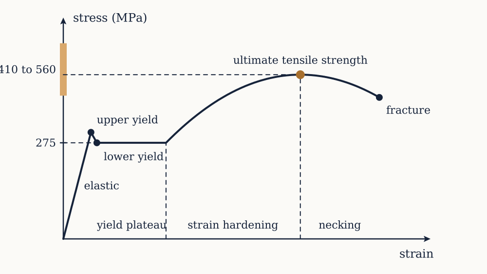
Pull a mild steel specimen past the straight portion and five things happen in order, each with a name.
The proportional limit is where the line stops being straight. Just above it lies the elastic limit, the last stress from which the specimen returns to its original length on unloading; in practice the two are close enough that most texts do not distinguish them.
Then mild steel does something unusual and useful: it yields at a well defined stress, and the load actually drops slightly, from an upper to a lower yield point, before the specimen extends at essentially constant load for a strain of one or two per cent. That flat plateau is the yield plateau, and while it is happening bands of sheared material called Lüders bands sweep visibly along the specimen.
After the plateau the material strain hardens and the curve rises again, because the dislocations that carry plastic flow get tangled and impede one another. The peak of the curve is the ultimate tensile strength, the largest engineering stress the specimen sustains.
Past the peak the curve falls, and the fall is a geometric effect rather than a weakening. Deformation localises into a neck where the section is thinning faster than the material is hardening, all further elongation happens in that neck, and the load needed to continue drops even though the material there is getting stronger. Fracture ends it.
For grade S275 structural steel, the yield strength is MPa, the ultimate strength lies between about and MPa, and the elongation at fracture is around per cent. For S355 the yield is MPa and the ultimate between about and MPa. That gap between yield and ultimate is a large part of why steel is a forgiving material: a member that has just started to yield still has half as much again in reserve before anything parts.
Reading a test
Example. A tensile specimen of mm diameter is machined with a mm gauge length. It yields at kN, reaches a maximum load of kN, and breaks; afterwards the gauge length measures mm and the diameter at the neck is mm. Find the yield strength, the ultimate strength, the percentage elongation and the reduction of area.
The original area is mm². The yield strength is MPa and the ultimate strength is MPa, both computed on the original area by convention. The elongation is per cent. The reduction of area is per cent. Those last two are the standard measures of ductility, and a metal with a few per cent of either is one to be careful with.
Now you. A specimen of mm diameter and mm gauge length yields at kN, peaks at kN, and finishes with a gauge length of mm. Find the yield strength, the ultimate strength and the elongation.
Answer
The area is mm². Yield is MPa, ultimate is MPa, and the elongation is per cent. That is roughly an S355 steel.
Engineering stress uses the original area throughout, which is why the curve appears to fall after the peak. True stress, load divided by the actual current area, rises monotonically all the way to fracture. At maximum load the specimen above has extended by about per cent uniformly, so its area has shrunk by about the same factor, and the true stress there is nearer MPa than . Design uses engineering stress because the original dimensions are the ones on the drawing, and metal forming uses true stress because it cares what the material is actually doing.
When there is no yield point
Most materials do not oblige with a plateau. Aluminium alloys, copper, high strength steels and most polymers curve away from the straight line gradually, with no single stress at which yielding obviously begins.
The convention is the 0.2 per cent proof stress, sometimes written or : draw a line parallel to the elastic portion, offset by a strain of , and take the stress where it cuts the curve. That is the stress which leaves per cent permanent strain after unloading, which for a 3 metre member is mm of set. Aluminium alloy 6082-T6, the common structural extrusion alloy, has a proof stress near MPa and an ultimate strength near MPa, so its margin between first yield and fracture is far narrower than steel's.
The definition is arbitrary and it is honest about being arbitrary. Nothing physical happens at ; the number is chosen because it is measurable, reproducible and small enough not to matter.
Ductile and brittle
The distinction that governs how a structure fails is whether the material can deform plastically before it parts.
A ductile material yields, redistributes, warns, and absorbs energy. Its tensile and compressive strengths are similar, it is insensitive to stress concentrations under steady load, and it fails on a slanted surface driven by shear. Mild steel, copper, aluminium and most polymers above their glass transition behave this way.
A brittle material fractures with almost no plastic strain, at a stress set by the worst flaw it happens to contain. Its strength is scattered rather than a number, it is far stronger in compression than in tension, it is acutely sensitive to notches, and it gives no warning. Grey cast iron has a tensile strength near MPa and a compressive strength near MPa. Concrete is more extreme still: a common structural grade takes to MPa in compression and about a tenth of that in tension, which is why every concrete design assumes the tension side has already cracked and puts steel there.
The distinction is not a permanent property of a substance. Steel that is ductile at degrees Celsius becomes brittle below a transition temperature, and the transition can sit near ordinary ambient conditions in the wrong composition. Of the 2710 all-welded Liberty ships built during the Second World War, hundreds developed serious hull cracks in cold North Atlantic service and about twenty broke essentially in two. The most quoted case is not a Liberty ship at all but the T2 tanker Schenectady, which split across its deck and down both sides at its outfitting dock in Portland, Oregon, on 16 January 1943, having never been to sea. The investigations that followed established low temperature brittle fracture as a design case and made the Charpy impact test, devised by Georges Charpy in 1901, a routine acceptance requirement for ship plate.
Toughness, and the number a hardness tester gives
The area under the stress-strain curve up to fracture is the energy absorbed per unit volume, and it is the material's toughness. It has units of joules per cubic metre, which reduce to pascals, so toughness is numerically comparable with strength while meaning something entirely different.
Strength and toughness pull against each other. A hardened tool steel may have three times the yield strength of mild steel and a tenth of its elongation, so its toughness is lower despite its strength being higher. For anything that might be struck, dropped, or loaded by an event nobody predicted, toughness is the property that decides whether the structure deforms or shatters, and it is the reason a car body is made of a steel far weaker than the best available.
Hardness is the cheap proxy. A Brinell or Vickers test presses an indenter into the surface and reports load divided by indentation area, and because indentation is essentially a constrained plastic flow it correlates with tensile strength. For steels the rule of thumb is that the ultimate strength in megapascals is roughly times the Brinell number, so a hardness of HB suggests about MPa. It is a correlation and not a law, it is calibrated separately for each family of alloys, and it says nothing at all about ductility. Its value is that it is non-destructive and takes a minute, which makes it the standard check on a component that has already been made.
Factors of safety
No structure is designed to reach the stress at which its material fails. The traditional method sets an allowable stress, the yield or ultimate strength divided by a factor of safety, and requires the calculated working stress to stay below it.
The factor is not one number for all time. Victorian practice used four or more on the ultimate strength for cast iron, reflecting scattered material, crude analysis and an unforgiving failure mode. Modern structural steelwork works closer to on yield, because the material is delivered to a specification with a guaranteed minimum, the analysis is far better, and the failure mode gives warning. Lifting equipment and pressure vessels sit between. The factor is covering ignorance about the load, ignorance about the material, ignorance about the analysis, and the consequences of being wrong, and it shrinks precisely as those become better known.
Example. A tie carries kN. It is to be made from S275 steel with a factor of safety of on yield. What area is needed, and would a mm square bar do?
The allowable stress is MPa, so the area required is mm². A mm square bar has mm², so it is adequate, and its working stress is MPa, giving an actual factor on yield of .
Now you. A tie carries kN in S355 steel with a factor of safety of . What area is needed?
Answer
The allowable stress is MPa, so the area required is mm². A mm square bar at mm² would just do it.
Where the margin goes in modern codes
Dividing the strength by one number treats all uncertainty as though it lived in the material, which it does not. The self-weight of a concrete slab is known to a few per cent; the crowd load on the floor above it is not. Applying the same margin to both is either wasteful for one or unsafe for the other.
Modern codes therefore use partial factors, putting a separate factor on each source of uncertainty. In the Eurocodes the usual persistent design combination multiplies permanent actions by and the leading variable action by , then compares the result against a resistance found using material strengths divided by their own factors: for steel yielding, for reinforcement, for concrete in compression. Concrete gets the largest material factor because it is made on site and its strength varies most.
Example. A floor beam of m span carries a permanent load of kN m⁻¹ and a variable load of kN m⁻¹. Find the design bending moment.
The design load is kN m⁻¹. The beam is simply supported, so kN m. The section then has to be chosen so that its moment resistance, computed with the material factor already applied, is at least that.
Now you. A beam of m span carries kN m⁻¹ permanent and kN m⁻¹ variable. Find the design moment.
Answer
The design load is kN m⁻¹, and kN m.
What a factor of safety does not cover
A factor on yield protects against a member being overloaded once, by a static load, at room temperature, in a member with no defects. Four common failures escape it entirely.
Fatigue cracks grow under loads far below yield, provided they are repeated often enough: a welded steel detail may have a fatigue limit under MPa at a few million cycles, well inside any static allowable stress. Fracture propagates from an existing crack when the material's toughness is exceeded, which is governed by crack length and fracture toughness rather than by stress alone. Creep lets a material deform steadily under constant load at high temperature, which is why turbine blades and steam pipes are designed to a stress that limits creep rate rather than to yield. And corrosion, which quietly removes the area every one of these calculations divided by.
Each of those is a subject on its own, and naming them is the point: a stress calculation with a factor of safety on it is a necessary condition and never a sufficient one.
With the material curve in hand, the rest of the course goes back to geometry. Every result so far has assumed the stress is spread evenly over the section, so only the size of a member mattered. The next lesson breaks that assumption for the first time, and once it is broken, shape becomes the main thing an engineer chooses.