Axial force, torsion, bending and shear have each been treated as though a member carried nothing else. Almost no member obliges. A column carries its load and the wind, a crank carries torque and bending, a masonry pier carries a load that is never quite where the drawing says. Combining them is partly simple addition and partly something new, because two stresses acting in different directions cannot be added at all.
Adding axial and bending stress
Where two actions produce normal stress on the same plane, the stresses add directly, because the elastic problem is linear and superposition holds. A member carrying an axial force and a bending moment has
with the plus at the fibre where bending is tensile and the minus at the other. The two extreme fibres are no longer equally stressed, and the neutral axis moves off the centroid or leaves the section altogether.
That is the whole of it for stresses of the same kind on the same plane. What cannot be done is to add a normal stress to a shear stress: they act in different directions on the face and their sum has no meaning. That case needs the transformation later in this lesson.
Eccentric load and the middle third
The commonest source of combined axial and bending stress is not a separate moment at all, but an axial load applied off centre. A load at an eccentricity from the centroid is statically equivalent to a load on the centroid plus a moment , so
For materials that cannot take tension, and masonry, plain concrete, soil under a footing and dry stone walling are all in that category, the design question is where the load may be applied without the far face going into tension. Setting the smaller stress to zero,
For a rectangular section of depth , . So the load may be up to one sixth of the depth from the centre in either direction, which means it must land within the middle third of the section. This is the middle third rule, and it governs the proportions of gravity dams, retaining walls, masonry piers and pad foundations. The two-dimensional version of the same argument gives a diamond-shaped kern in the middle of the section, within which a load produces no tension anywhere.
Example. A masonry pier is mm wide and mm deep and carries kN at an eccentricity of mm along the mm direction. Find the stresses at the two faces.
mm² and mm³. The direct stress is MPa and the bending stress is MPa. So the faces carry MPa and MPa, both compressive. The middle third limit is mm, and mm is inside it, which the arithmetic has just confirmed.
Now you. The same pier carries the same load at an eccentricity of mm. What happens?
Answer
The bending stress becomes MPa, so the faces carry MPa compression and MPa tension. The eccentricity is outside the middle third, the mortar joint on the far face opens, and the real stress distribution redistributes over a reduced contact area at a higher peak than this calculation shows.
The state of stress at a point
Cut through a loaded body at a point, and the face exposed carries a normal stress and a shear stress. Cut through the same point at a different angle and both are different. So "the stress at a point" is not one number, and the useful question is what the smallest complete description is.
In two dimensions it is three numbers: and , the normal stresses on faces perpendicular to two chosen axes, and , the shear stress on those faces, which by complementary shear is the same on both. Everything else follows.
Take a small wedge whose sloping face is at an angle to the axis, and impose equilibrium on it. Resolving normal and parallel to the sloping face, and using the fact that the areas of the three faces are in the ratio of cosines and sines, gives the transformation equations
Both are equilibrium results. No material property appears, so they hold for steel, concrete, soil and rubber alike.
Principal stresses
The angle at which vanishes is found by setting the second equation to zero:
On those planes the stress is purely normal, and differentiating the first equation shows they are also where is largest and smallest. These are the principal stresses
and the two principal planes are ninety degrees apart, since has solutions degrees apart. The maximum shear stress is the radical on its own,
and it occurs on planes at degrees to the principal ones.
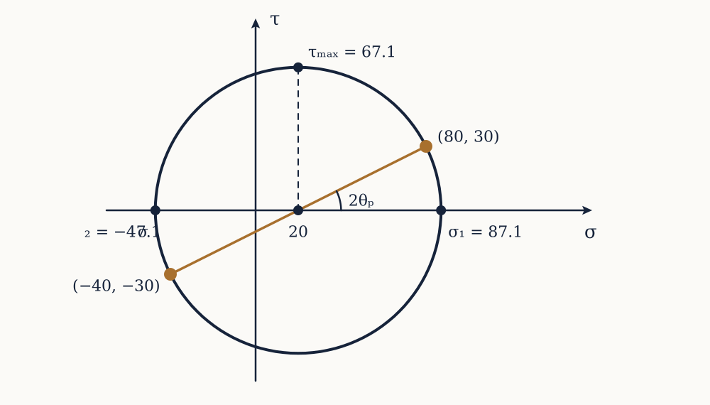
Example. At a point, MPa, MPa and MPa. Find the principal stresses, the maximum shear stress, and the orientation of the principal planes.
The average is MPa. The radical is MPa. So MPa and MPa, and MPa. The orientation comes from , giving degrees and degrees.
Now you. At another point, MPa, MPa and MPa. Find the principal stresses and the maximum shear stress.
Answer
The average is MPa and the radical is MPa. So MPa, MPa, and MPa. Note that both principal stresses are tensile, yet the maximum shear stress is nearly half the larger of them.
Mohr's circle
The two transformation equations are the parametric equations of a circle in a plane whose horizontal axis is normal stress and whose vertical axis is shear stress. Squaring and adding them eliminates and leaves
a circle centred on the average stress with radius equal to the maximum shear stress. Every plane through the point corresponds to one location on that circle, and rotating the cutting plane by moves the point round the circle by .
Otto Mohr published this construction in 1882, building on a graphical method of Karl Culmann's from 1866, and in an era before calculators it was how the work was done. It survives because it makes the relationships visible in a way the algebra does not: the principal stresses are where the circle crosses the horizontal axis, the maximum shear is the top of the circle, planes ninety degrees apart in the material are diametrically opposite on the circle, and a state of hydrostatic stress is a circle of zero radius with no shear on any plane at all.
Pure shear, and the helix in a broken shaft
Apply the machinery to the simplest interesting case, a point in pure shear with and , which is what the torsion lesson found at the surface of a twisted shaft.
The average is zero and the radical is , so and , on planes at degrees. Pure shear is equal tension and compression at forty-five degrees to it, seen from a different angle.
That result explains a pair of observations anyone can make. Twist a piece of chalk until it breaks and the fracture is a clean helical surface at about degrees to the axis, because chalk is brittle and fails on the plane of maximum tensile stress. Twist a mild steel bar and it fails on a flat cross section perpendicular to the axis, because steel is ductile and fails on the plane of maximum shear, which for a shaft in torsion is the cross section itself. The failure surface tells you which criterion the material obeyed.
Yield criteria
The tensile test gives one number, , obtained under a state of stress with one non-zero component. A point in a real structure has three. A yield criterion is a rule for boiling the three back down to one equivalent stress that can be compared with the test.
The Tresca criterion, from Henri Tresca's extrusion experiments in the 1860s, says yielding begins when the maximum shear stress reaches the value it had at yield in the tensile test. In a tensile test at yield, and , so . The criterion is therefore .
The von Mises criterion, associated with Richard von Mises in 1913 and with Maxwell and Huber before him, says yielding begins when the distortion energy per unit volume reaches its tensile-test value. In plane stress it reads .
For the common engineering case of a normal stress combined with a shear stress , both reduce to something usable:
Tresca is always the more conservative of the two, by at most about per cent, which happens in pure shear where Tresca predicts yielding at and von Mises at . Experiments on ductile metals sit closer to von Mises, so codes generally use it and Tresca survives as the simpler hand check.
Neither applies to a brittle material, which does not yield at all. For cast iron, stone or concrete, the governing criterion is a maximum tensile stress or a more elaborate rule that treats tension and compression differently, and using von Mises on concrete is a category error rather than a conservative approximation.
Example. A solid steel shaft of mm diameter carries a bending moment of kN m and a torque of kN m at the same section. Find the factor of safety against yield at MPa, by both criteria.
The section modulus in bending is mm³, so MPa. The torsional modulus is mm³, so MPa. Then
giving factors of and . Note that neither of the two individual stresses was anywhere near MPa, and the combination is still the thing that decides.
Now you. The same shaft carries kN m of bending and kN m of torque. Find both equivalent stresses.
Answer
MPa and MPa. Tresca gives MPa and von Mises MPa.
What combining does not fix
Superposition is a property of linear elastic behaviour, and it fails wherever that fails. Once part of a section has yielded, the stresses from two actions no longer simply add, which is why plastic design of a beam-column uses interaction formulas fitted to tests rather than a sum of terms.
It also fails where one action changes the geometry that the other acts on. A column carrying compression and bending deflects sideways, and the compression then acts at that new eccentricity, adding more moment: the load amplifies its own effect. That second-order behaviour is exactly the buckling amplification of the previous lesson, and it is why a beam-column is checked with an interaction equation containing an amplification factor rather than by adding to and stopping.
Everything in the course to this point sizes a member: which section, how deep, how thick. One choice has been assumed throughout and never examined, which is what the member should be made of. Making that choice properly turns out to fold most of this course into a single number per material, and it is the last lesson.