A boiler transfers heat from flames at K into steam at K across a tube wall, and the largest single loss in a steam plant is that transfer, which no rearrangement of the steam cycle can touch.
Burn it in the working fluid
The way past the tube wall is to stop having one. Compress air, inject fuel into it, burn the mixture, and expand the hot products through a turbine. The combustion products are the working fluid, so the heat never has to cross a surface, and the fluid can reach whatever temperature the turbine blades will survive rather than whatever a boiler tube will survive.
The price is that the working fluid is consumed. Air is drawn in from atmosphere, and the exhaust is dumped back to atmosphere rather than recirculated, so this is an open cycle and not a cycle at all in the strict sense. It is treated as one by the usual idealisation: replace the combustion with heat addition from an external source, replace the exhaust and fresh intake with heat rejection to the surroundings, and take the working fluid to be air throughout. That is the air-standard assumption, and with constant specific heats evaluated at room temperature it is the cold-air-standard assumption used below.
What results is the Brayton cycle, named for George Brayton, who patented a piston version in . It has four processes: isentropic compression, constant-pressure heat addition, isentropic expansion, constant-pressure heat rejection. Every one of them happens in a steady-flow device already analysed.
Everything follows from the pressure ratio
Label the states: at compressor inlet, at compressor exit, at turbine inlet after combustion, at turbine exit. Both heat exchanges are at constant pressure, so
and both machines are adiabatic, so and .
For the ideal cycle both machines are isentropic, and the isentropic relation gives and with the same pressure ratio , since states and share a pressure and so do and . Writing for brevity, the efficiency is
after cancelling. So
The ideal Brayton efficiency depends on the pressure ratio and nothing else. Not on the peak temperature, not on the fuel, not on the size of the machine. That is a startling result and it is worth being suspicious of, because it is exactly the kind of clean statement that survives only in the idealisation.
Example. An ideal Brayton cycle takes air at K and kPa, compresses it with a pressure ratio of , and heats it to K. With kJ kg⁻¹ K⁻¹ and , find the state temperatures, the net work and the efficiency.
The exponent is and . So K and K. The compressor absorbs kJ kg⁻¹ and the turbine delivers kJ kg⁻¹, so kJ kg⁻¹. The heat input is kJ kg⁻¹, giving , which the formula confirms as .
Now you. The same cycle at a pressure ratio of . Find the temperatures, the net work and the efficiency.
Answer
, so K and K. The compressor takes kJ kg⁻¹ and the turbine gives , so kJ kg⁻¹. With kJ kg⁻¹, .
The back work ratio decides whether it can be built
Compare those numbers with the steam plant. The steam cycle's pump absorbed per cent of the turbine output. Here the compressor absorbs of it, and at higher pressure ratios more: at , at .
That is the whole reason gas turbines are a twentieth-century technology while steam engines are an eighteenth-century one. The concept is old, and John Barber patented something recognisable in . The obstacle was that with a compressor of per cent efficiency and a turbine of per cent, the arithmetic gives a net output of approximately nothing. Aurel Stodola calculated in that no useful gas turbine was then possible, and he was right about the machines that existed. The first units that ran usefully, in the late s, did so because aerodynamic compressor design had finally reached the low eighties per cent.
That sensitivity persists. In a steam plant the pump can be twenty points off and nobody notices. In a gas turbine, two points of compressor efficiency is a fifth of a point on the whole cycle at best and a project at worst.
What real machines do to it
Put in real efficiencies and the clean result about pressure ratio falls apart in an instructive way.
Example. The same cycle, and K, but with a compressor of isentropic efficiency and a turbine of . Find the net work, the efficiency and the back work ratio.
The isentropic values stand as references: and kJ kg⁻¹. The real compressor absorbs kJ kg⁻¹, so the air leaves it at K rather than K. The real turbine delivers kJ kg⁻¹, exhausting at K. Net work is kJ kg⁻¹, nearly half what the ideal cycle gave. The heat input falls too, since the air enters the combustor hotter: kJ kg⁻¹. So , and the back work ratio has risen to .
Now you. Modern machines do better. Repeat with and .
Answer
kJ kg⁻¹ so K; kJ kg⁻¹ so K. Net work is kJ kg⁻¹ against , giving and a back work ratio of . Five points on each machine bought seven points on the cycle.
Notice what has happened to the clean formula. With real machines the efficiency depends on the peak temperature after all, because the losses are fixed fractions of work terms that scale differently with . Raising the turbine inlet temperature now raises efficiency, which is why the entire history of gas turbine development is a history of turbine inlet temperature: about K in , around K in current heavy-duty machines, achieved with internally cooled single-crystal blades and ceramic thermal barrier coatings, in gas that is hotter than the melting point of the alloy underneath.
The optimum pressure ratio
Efficiency rises without limit as the pressure ratio rises, but net work does not. At low the temperature rise available for heat addition is large but the expansion is short; at high the compressor exit approaches the turbine inlet temperature and there is nothing left to burn. Somewhere between, the work per kilogram peaks.
Differentiating with respect to and setting it to zero gives , or
For that is , where kJ kg⁻¹ against at and at . The peak is flat, which is fortunate, and it sits well below the pressure ratio that would maximise efficiency.
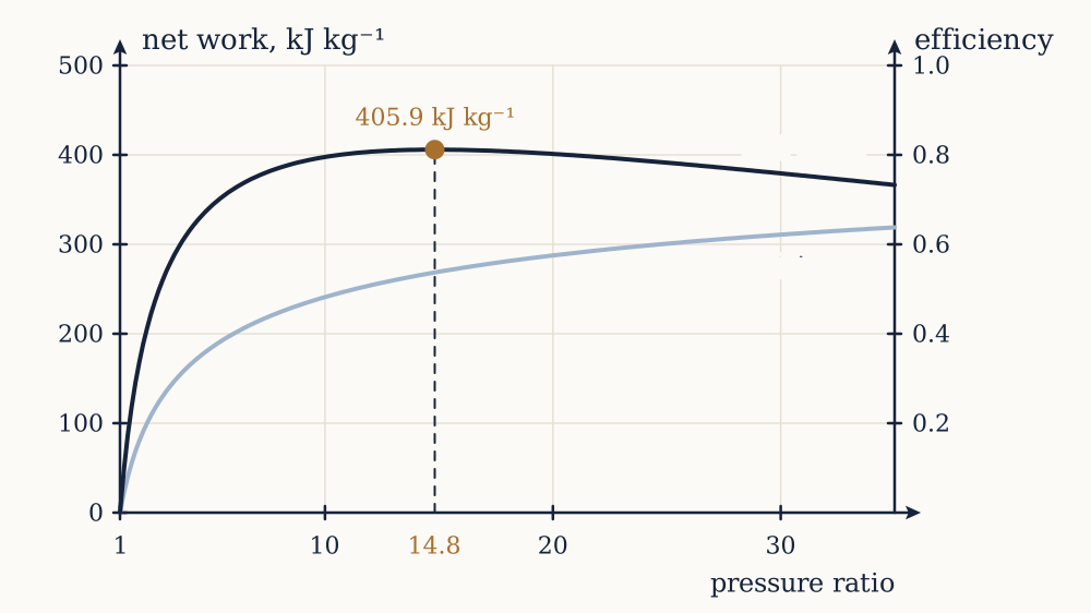
The two criteria pull apart, and which one matters depends on the machine. Aircraft engines are weight-limited, so they chase work per kilogram of air and run near the work optimum. Stationary machines that feed a steam cycle underneath care about neither in isolation, as the next lesson shows.
Regeneration
At the ideal cycle exhausts at K and delivers air to the combustor at K. The exhaust is hotter than the compressor discharge, so some of it can be used to preheat the air before combustion, exactly as bled steam preheats feedwater in a Rankine plant. The device is a regenerator, a gas-to-gas heat exchanger, and its effectiveness is
where is the temperature reached by the compressed air after preheating. Fuel is then only needed from to .
Example. Fit the ideal cycle with a regenerator of effectiveness . Find the new heat input and efficiency.
K, so kJ kg⁻¹. The work is unchanged at kJ kg⁻¹, so , up from .
Now you. An older regenerator manages only . What efficiency results?
Answer
K, so kJ kg⁻¹ and .
Regeneration has a hard limit that the formula makes obvious. It works only while , and for the ideal cycle those are equal when , that is at : exactly the pressure ratio that maximises net work. Above it the compressor discharge is hotter than the exhaust and a regenerator would move heat the wrong way. So regeneration belongs to low-pressure-ratio machines, and modern high-pressure-ratio units do not use it. They use the exhaust differently, which is the next lesson.
Jet propulsion, and where the model gives out
Change one thing and the same cycle becomes a jet engine: size the turbine to produce exactly the work the compressor needs and no more, then let the remaining pressure expand through a nozzle instead of further turbine stages. The output is not shaft work but a high-velocity jet, and the thrust is . An engine passing kg s⁻¹ with an exit velocity of m s⁻¹ on an aircraft flying at m s⁻¹ produces kN. The diffuser at the intake, analysed several lessons ago, does part of the compression for free once the aircraft is moving.
Three limits deserve naming before the results above are trusted too far.
The cold-air-standard assumption uses kJ kg⁻¹ K⁻¹ throughout, but the specific heat of air rises with temperature and combustion products differ in composition from air. At K the real value is nearer kJ kg⁻¹ K⁻¹, so the analysis above overstates the efficiency by several points. Using air tables with variable specific heats fixes most of it, and using real gas composition fixes the rest.
The fuel is ignored. Adding fuel increases the mass flow through the turbine relative to the compressor by two or three per cent, which helps the real machine slightly, and the combustor has its own pressure drop of three to five per cent, which hurts.
Turbine cooling is not free. Air bled from the compressor to cool the first turbine stages has been compressed and then does not pass through the combustor, so it produces less work than it cost. In a machine at K, fifteen to twenty per cent of the compressor flow can be doing this, and every efficiency quoted for a real machine already has it subtracted.
The larger point survives all three. Even with a good compressor and turbine, this cycle exhausts at K and throws the whole of it away, which is why a bare gas turbine reaches only the mid-thirties per cent. That exhaust is a heat source at nearly K, and there is a cycle that would very much like a heat source at nearly K.